ecoTEC pro - Vaillant
ecoTEC pro - Vaillant
ecoTEC pro - Vaillant

Create successful ePaper yourself
Turn your PDF publications into a flip-book with our unique Google optimized e-Paper software.
10 Commissioning<br />
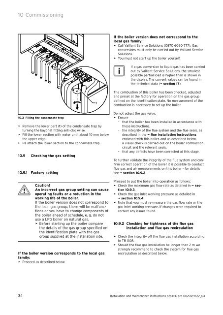
10.3 Filling the condensate trap<br />
> Remove the lower part (1) of the condensate trap by<br />
turning the bayonet fitting anti-clockwise.<br />
> Fill the lower section with water until about 10 mm below<br />
the upper edge.<br />
> Re-attach the lower section to the condensate trap.<br />
10.9 Checking the gas setting<br />
10.9.1 Factory setting<br />
b<br />
Caution!<br />
An incorrect gas group setting can cause<br />
operating faults or a reduction in the<br />
working life of the boiler.<br />
If the boiler version does not correspond to<br />
the local gas group, there will be malfunctions<br />
or you have to change components of<br />
the boiler ahead of schedule, e. g. do not<br />
use a LPG boiler on natural gas.<br />
> Before starting up the boiler compare<br />
the details of the gas group specified on<br />
the identification plate with the gas<br />
group supplied at the installation site.<br />
If the boiler version corresponds to the local gas<br />
family:<br />
> Proceed as described below.<br />
1<br />
If the boiler version does not correspond to the<br />
local gas family:<br />
> Call <strong>Vaillant</strong> Service Solutions (0870 6060 777); Gas<br />
conversions must only be carried out by <strong>Vaillant</strong> Service<br />
Solutions.<br />
> You must not start up the boiler yourself.<br />
i If<br />
a gas conversion to liquid gas has been carried<br />
out by <strong>Vaillant</strong> Service Solutions, the smallest<br />
possible partial load is higher than is shown in<br />
the display. The current values can be found in<br />
the technical data (¬ section 17).<br />
The combustion of this boiler has been checked, adjusted<br />
and preset at the factory for operation on the gas group<br />
defined on the identification plate. No measurement of the<br />
combustion is necessary to set up the boiler.<br />
Do not adjust the gas valve.<br />
> Ensure<br />
– that the boiler has been installed in accordance with<br />
these instructions,<br />
– the integrity of the flue system and the flue seals, as<br />
described in the ¬ flue installation instructions<br />
enclosed with this boiler, and as described below,<br />
– a visual check is carried out on the boiler combustion<br />
circuit and the relevant seals,<br />
– that any defects have been corrected at this stage.<br />
To further validate the integrity of the flue system and confirm<br />
correct operation of the boiler it is possible to conduct<br />
flue gas and air measurements on this boiler - for details<br />
see ¬ section 10.9.2.<br />
Proceed to put the boiler into operation as follows:<br />
> Check the maximum gas flow rate as detailed in ¬ section<br />
10.9.3.<br />
> Check the gas inlet working pressure as detailed in<br />
¬ section 10.9.4.<br />
> Note that you must re-measure the gas flow rate or the<br />
gas inlet working pressure, if changes were required to<br />
correct any issues found.<br />
10.9.2 Checking for tightness of the flue gas<br />
installation and flue gas recirculation<br />
> Check the integrity off the flue gas installation according<br />
to TB 008.<br />
> Should the flue gas installation be longer than 2 m we<br />
strongly recommend to check the system for flue gas<br />
recirculation as described below.<br />
34 Installation and maintenance instructions <strong>ecoTEC</strong> <strong>pro</strong> 0020129672_03