ecoTEC pro - Vaillant
ecoTEC pro - Vaillant
ecoTEC pro - Vaillant

Create successful ePaper yourself
Turn your PDF publications into a flip-book with our unique Google optimized e-Paper software.
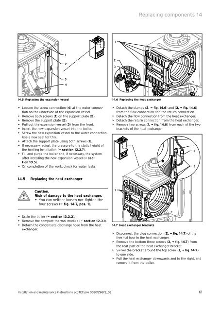
14.5 Replacing the expansion vessel<br />
> Loosen the screw connection (4) at the water connection<br />
on the underside of the expansion vessel.<br />
> Remove both screws (1) on the support plate (2).<br />
> Remove the support plate (2).<br />
> Pull out the expansion vessel (3) from the front.<br />
> Insert the new expansion vessel into the boiler.<br />
> Screw the new expansion vessel to the water connection.<br />
Use a new seal for this.<br />
> Attach the support plate using both screws (1).<br />
> If necessary, adjust the pressure to the static height of<br />
the heating installation (¬ section 12.3.7).<br />
> Fill and purge the boiler and, if necessary, the system<br />
after installing the new expansion vessel (¬ section<br />
10.5).<br />
> On completion of the work, check for water leaks.<br />
14.5 Replacing the heat exchanger<br />
b Caution.<br />
Risk of damage to the heat exchanger.<br />
> You can neither loosen nor tighten the<br />
four screws (¬ fig. 14.7, pos. 1).<br />
> Drain the boiler (¬ section 12.2.2).<br />
> Remove the compact thermal module (¬ section 12.3.1).<br />
> Detach the condensate discharge hose from the heat<br />
exchanger.<br />
1<br />
2<br />
3<br />
4<br />
Replacing components 14<br />
Installation and maintenance instructions <strong>ecoTEC</strong> <strong>pro</strong> 0020129672_03 61<br />
1<br />
2<br />
3<br />
14.6 Replacing the heat exchanger<br />
> Detach the clamps (2, ¬ fig. 14.6) and (3, ¬ fig. 14.6)<br />
from the flow connection and the return connection.<br />
> Detach the flow connection from the heat exchanger.<br />
> Detach the return connection from the heat exchanger.<br />
> Remove two screws (1, ¬ fig. 14.6) from each of the two<br />
brackets of the heat exchanger.<br />
1<br />
14.7 Heat exchanger brackets<br />
> Disconnect the plug connection (2, ¬ fig. 14.7) of the<br />
thermal fuse in the heat exchanger.<br />
> Remove the bottom three screws (3, ¬ fig. 14.7) from<br />
the rear part of the heat exchanger bracket.<br />
> Swivel the bracket around the top screw (1, ¬ fig. 14.7)<br />
to one side.<br />
> Pull the heat exchanger downwards and to the right, and<br />
remove it from the boiler.<br />
1<br />
2<br />
3