ecoTEC pro - Vaillant
ecoTEC pro - Vaillant
ecoTEC pro - Vaillant

Create successful ePaper yourself
Turn your PDF publications into a flip-book with our unique Google optimized e-Paper software.
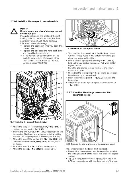
12.3.6 Installing the compact thermal module<br />
a<br />
Danger!<br />
Risk of death and risk of damage caused<br />
by hot flue gas!<br />
If you do not renew the seal and the selflocking<br />
nuts on the burner door, hot flue<br />
gases may escape and cause personal<br />
injury and material damage.<br />
> Replace the seal each time you open the<br />
burner door.<br />
> Replace the self-securing nuts each time<br />
you open the burner door.<br />
> If the burner flange insulation on the<br />
module shows signs of damage other<br />
than small cracks it must be replaced<br />
(article number 193 595).<br />
10<br />
9<br />
8<br />
7<br />
12.10 Installing the compact thermal module<br />
> Attach the compact thermal module (4, ¬ fig. 12.10) to<br />
the heat exchanger (1, ¬ fig. 12.10).<br />
> Tighten the four nuts (3, ¬ fig. 12.10) crosswise until the<br />
burner door fits closely and uniformly onto the mating<br />
surfaces (If a torque spanner is available, set at 6 Nm).<br />
> Attach the plug of the ignition line (10, ¬ fig. 12.10) and<br />
the ground connection (9, ¬ fig. 12.10) to the ignition<br />
electrode.<br />
> Attach the plug (5, ¬ fig. 12.10) to the fan motor.<br />
> Attach the plug (8, ¬ fig. 12.10) to the gas valve.<br />
1<br />
2<br />
3<br />
4<br />
5<br />
6<br />
Inspection and maintenance 12<br />
12.11 Secure the gas pipe against twisting<br />
> Tighten either the cap nut (6, ¬ fig. 12.10) on the gas<br />
valve or the cap nut (7, ¬ fig. 12.10) between the gas<br />
pipes. Use a new seal for this.<br />
> Secure the gas pipe against twisting (¬ fig. 12.11) by<br />
holding the pipe against the spanner flat when tightening<br />
the cap nut.<br />
> Open the gas isolator cock on the boiler and ensure<br />
there are no leaks.<br />
> Check that the sealing ring in the air intake pipe is positioned<br />
correctly in the seal seat.<br />
> Insert the air intake pipe (1, ¬ fig. 12.3) back into the<br />
intake stub.<br />
> Attach the air intake pipe using the retaining screw (2,<br />
¬ fig. 12.3).<br />
12.3.7 Checking the charge pressure of the<br />
expansion vessel<br />
12.12 Checking the charge pressure of the expansion vessel<br />
The service valves of the boiler must be closed.<br />
> Measure the charge pressure of the expansion vessel at<br />
the testing nozzle (1) of the vessel with the boiler depressurised.<br />
> Top up the expansion vessel at a pressure of less than<br />
0.75 bar in accordance with the static height of the heat-<br />
Installation and maintenance instructions <strong>ecoTEC</strong> <strong>pro</strong> 0020129672_03 53<br />
1