Bill Acceptor
Bill Acceptor
Bill Acceptor

You also want an ePaper? Increase the reach of your titles
YUMPU automatically turns print PDFs into web optimized ePapers that Google loves.
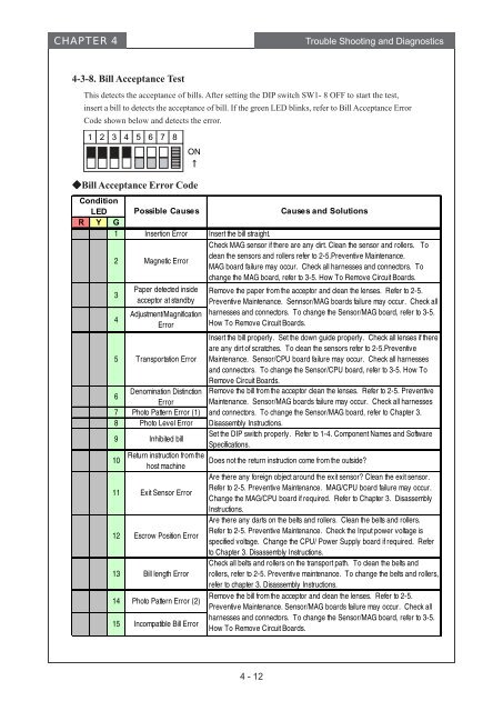
CHAPTER 4 Trouble Shooting and Diagnostics<br />
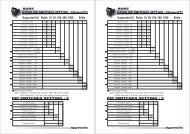
4-3-8. <strong>Bill</strong> Acceptance Test<br />
This detects the acceptance of bills. After setting the DIP switch SW1- 8 OFF to start the test,<br />
insert a bill to detects the acceptance of bill. If the green LED blinks, refer to <strong>Bill</strong> Acceptance Error<br />
Code shown below and detects the error.<br />
1 2 3 4 5 6 7 8<br />
ON<br />
<strong>Bill</strong> Acceptance Error Code<br />
Condition<br />
LED Possible Causes Causes and Solutions<br />
R Y G<br />
1 Insertion Error Insert the bill straight.<br />
2 Magnetic Error<br />
Check MAG sensor if there are any dirt. Clean the sensor and rollers. To<br />
clean the sensors and rollers refer to 2-5.Preventive Maintenance.<br />
MAG board failure may occur. Check all harnesses and connectors. To<br />
change the MAG board, refer to 3-5. How To Remove Circuit Boards.<br />
3<br />
4<br />
Paper detected inside<br />
acceptor at standby<br />
Adjustment/Magnification<br />
Error<br />
5 Transportation Error<br />
Denomination Distinction<br />
6<br />
Error<br />
7 Photo Pattern Error (1)<br />
8 Photo Level Error<br />
9 Inhibited bill<br />
10<br />
Return instruction from the<br />
host machine<br />
11 Exit Sensor Error<br />
12 Escrow Position Error<br />
13 <strong>Bill</strong> length Error<br />
14 Photo Pattern Error (2)<br />
15 Incompatible <strong>Bill</strong> Error<br />
Remove the paper from the acceptor and clean the lenses. Refer to 2-5.<br />
Preventive Maintenance. Sennsor/MAG boards failure may occur. Check all<br />
harnesses and connectors. To change the Sensor/MAG board, refer to 3-5.<br />
How To Remove Circuit Boards.<br />
Insert the bill properly. Set the down guide properly. Check all lenses if there<br />
are any dirt of scratches. To clean the sensors refer to 2-5.Preventive<br />
Maintenance. Sensor/CPU board failure may occur. Check all harnesses<br />
and connectors. To change the Sensor/CPU board, refer to 3-5. How To<br />
Remove Circuit Boards.<br />
Remove the bill from the acceptor clean the lenses. Refer to 2-5. Preventive<br />
Maintenance. Sensor/MAG boards failure may occur. Check all harnesses<br />
and connectors. To change the Sensor/MAG board, refer to Chapter 3.<br />
Disassembly Instructions.<br />
Set the DIP switch properly. Refer to 1-4. Component Names and Software<br />
Specifications.<br />
Does not the return instruction come from the outside?<br />
Are there any foreign object around the exit sensor? Clean the exit sensor.<br />
Refer to 2-5. Preventive Maintenance. MAG/CPU board failure may occur.<br />
Change the MAG/CPU board if required. Refer to Chapter 3. Disassembly<br />
Instructions.<br />
Are there any darts on the belts and rollers. Clean the belts and rollers.<br />
Refer to 2-5. Preventive Maintenance. Check the Input power voltage is<br />
specified voltage. Change the CPU/ Power Supply board if required. Refer<br />
to Chapter 3. Disassembly Instructions.<br />
Check all belts and rollers on the transport path. To clean the belts and<br />
rollers, refer to 2-5. Preventive maintenance. To change the belts and rollers,<br />
refer to chapter 3. Disassembly Instructions.<br />
Remove the bill from the acceptor and clean the lenses. Refer to 2-5.<br />
Preventive Maintenance. Sensor/MAG boards failure may occur. Check all<br />
harnesses and connectors. To change the Sensor/MAG board, refer to 3-5.<br />
How To Remove Circuit Boards.<br />
4 - 12