Bill Acceptor
Bill Acceptor
Bill Acceptor

Create successful ePaper yourself
Turn your PDF publications into a flip-book with our unique Google optimized e-Paper software.
CHAPTER 5<br />
Software Download and Adjustment<br />
5-2. Adjustment<br />
This section describes how to adjust the DBV-30X unit. When the DBV-301 unit's Acceptance Rate get<br />
lower or DBV-30X unit’s CPU/MAG/Sensor board is replaced, please be sure to adjust the DBV-301 unit.<br />
5-2-1. Tools Required<br />
When adjusting the DBV-30X unit, the following items are required.<br />
- DBV-30X (with cash box)<br />
- PC (Windows (R) 98 SE/2000 with RS-232C Communication Port)<br />
- JCM Power Supply unit (VM300 (DC12V), Part No.:116477 or VM301 (DC24V), Part No.: 1164480)<br />
- JCM Communication cable (IFU-002, Part No.:100157) or<br />
(3280-03-15 Box 12V Relay Harness, Part No.:116490)<br />
- Adjustment Program Installer (setup.exe/SETUP.LST/Cab300.CAB)<br />
- White Reference Paper (KS-059, Part No.:111542)<br />
- Black Reference Paper 1 (KS-060, Part No.:111541)<br />
- Black Reference Paper 2 (KS-061, Part No.:111540)<br />
5-2-2. Installing the Adjustment Program (Cab300.exe)<br />
When installing the adjustment program (Cab300.exe), follow the staps as shown below.<br />
1) Copy the adjustment program installer (setup.exe/SETUP.LST/Cab300.CAB) to your PC.<br />
2) Double click the setup.exe to start the installation.<br />
3) Follow the instruction as shown on the screen and complete the installing.<br />
5-2-3. Initial Setting<br />
Before adjusting the DBV-30X unit, perform the following procedure.<br />
AC-Power<br />
Serial Port<br />
JCM Communication Cable<br />
(IFU-002)<br />
JCM Power Supply Unit<br />
(VM300 (DC12V) or<br />
VM301 (DC24V))<br />
DBV-30X<br />
PC<br />
(OS: Windows (R) 98 SE/2000)<br />
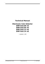
1) Refer to the diagram below to connect the cables/harnesses properly.<br />
- When connecting the harness to the DBV-30X unit, be sure the power of VM30X is OFF.<br />
Failure to do so may cause electric shock and/or permanent damage to the device.<br />
2) Set the SW1-8 ON and turn the VM30X unit’s power ON.<br />
3) Check the indication LEDs are blinking and the condition LED’s green, yellow and red LEDs light.<br />
This indicates the DBV-30X unit in the Test mode.<br />
5 - 6