
You also want an ePaper? Increase the reach of your titles
YUMPU automatically turns print PDFs into web optimized ePapers that Google loves.
Point Grey <strong>Blackfly</strong> Technical Reference<br />
2 <strong>Blackfly</strong> Installation<br />
4. Configure IP Settings<br />
After installation is complete, the Point Grey GigE Configurator opens. This tool allows you to configure the IP settings<br />
of the camera and network card.<br />
If the GigE Configurator does not open automatically, open the tool from Start Menu>FlyCapture<br />
SDK>Utilities>GigE Configurator. If prompted to enable GigE enumeration, select Yes.<br />
a. In the left pane, select the Local Area Connection corresponding to the network interface card (NIC) to which<br />
the camera is connected.<br />
b. In the right pane, review maximum transmission unit (MTU). If not 9000, enable jumbo frames on the NIC by<br />
clicking Open Network Connections. (While most NICs support 9000-byte jumbo frames, this feature is often<br />
disabled by default.)<br />
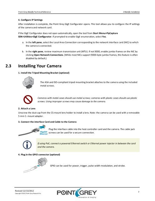
2.3 Installing Your Camera<br />
1. Install the Tripod Mounting Bracket (optional)<br />
The ASA and ISO-compliant tripod mounting bracket attaches to the camera using the included<br />
metal screws.<br />
Cameras with metal cases should use metal screws; cameras with plastic cases should use plastic<br />
screws. Using improper screws may cause damage to the camera.<br />
2. Attach a Lens<br />
Unscrew the dust cap from the CS-mount lens holder to install a lens. Note: the camera can be used with a removable<br />
5 mm C- mount adapter.<br />
3. Connect the interface Card and Cable to the Camera<br />
Plug the interface cable into the host controller card and the camera. The cable jack<br />
screws can be used for a secure connection.<br />
If using PoE, connect a powered Ethernet switch or Ethernet power injector in between the card<br />
and the camera.<br />
4. Plug in the GPIO connector (optional)<br />
GPIO can be used for power, trigger, pulse width modulation, and strobe.<br />
Revised 12/13/2012<br />
Copyright ©2012 Point Grey Research Inc.<br />
7