- Page 1 and 2:
s MC75 Siemens Cellular Engine Vers
- Page 3 and 4:
MC75 AT Command Set Contents s Cont
- Page 5 and 6:
MC75 AT Command Set Contents s 6.9
- Page 7 and 8:
MC75 AT Command Set Contents s 11.3
- Page 9 and 10:
MC75 AT Command Set Contents s 17.1
- Page 11 and 12:
MC75 AT Command Set List of Figures
- Page 13 and 14:
MC75 AT Command Set 1.2 Related doc
- Page 15 and 16:
MC75 AT Command Set 1.3 Document co
- Page 17 and 18:
MC75 AT Command Set 1.4 AT Command
- Page 19 and 20:
MC75 AT Command Set 1.5 Supported c
- Page 21 and 22:
MC75 AT Command Set 1.5 Supported c
- Page 23 and 24:
MC75 AT Command Set 1.5 Supported c
- Page 25 and 26:
MC75 AT Command Set 1.7 Unsolicited
- Page 27 and 28:
MC75 AT Command Set 1.9 Errors and
- Page 29 and 30:
MC75 AT Command Set 2.2 AT&V s 2.2
- Page 31 and 32:
MC75 AT Command Set 2.2 AT&V s Tabl
- Page 33 and 34:
MC75 AT Command Set 2.4 ATQ s 2.4 A
- Page 35 and 36:
MC75 AT Command Set 2.6 ATX s 2.6 A
- Page 37 and 38:
MC75 AT Command Set 2.8 ATZ s 2.8 A
- Page 39 and 40:
MC75 AT Command Set 2.9 AT+CFUN s U
- Page 41 and 42:
MC75 AT Command Set 2.9 AT+CFUN s E
- Page 43 and 44:
MC75 AT Command Set 2.11 AT+GCAP s
- Page 45 and 46:
MC75 AT Command Set 2.12 AT+CMEE s
- Page 47 and 48:
MC75 AT Command Set 2.12 AT+CMEE s
- Page 49 and 50:
MC75 AT Command Set 2.12 AT+CMEE s
- Page 51 and 52:
MC75 AT Command Set 2.14 AT^SCFG s
- Page 53 and 54:
MC75 AT Command Set 2.14 AT^SCFG s
- Page 55 and 56:
MC75 AT Command Set 2.14 AT^SCFG s
- Page 57 and 58:
MC75 AT Command Set 2.14 AT^SCFG s
- Page 59 and 60:
MC75 AT Command Set 2.14 AT^SCFG s
- Page 61 and 62:
MC75 AT Command Set 3. Status Contr
- Page 63 and 64:
MC75 AT Command Set 3.2 AT+CIND s 3
- Page 65 and 66:
MC75 AT Command Set 3.2 AT+CIND s N
- Page 67 and 68:
MC75 AT Command Set 3.3 AT^SIND s U
- Page 69 and 70:
MC75 AT Command Set 3.3 AT^SIND s u
- Page 71 and 72:
MC75 AT Command Set 3.3 AT^SIND s
- Page 73 and 74:
MC75 AT Command Set 3.4 AT+CEER s E
- Page 75 and 76:
MC75 AT Command Set 3.4 AT+CEER s N
- Page 77 and 78:
MC75 AT Command Set 3.4 AT+CEER s N
- Page 79 and 80:
MC75 AT Command Set 3.5 ATS18 s 3.5
- Page 81 and 82:
MC75 AT Command Set 3.6 AT+CPAS s 3
- Page 83 and 84:
MC75 AT Command Set 4. Serial Inter
- Page 85 and 86:
MC75 AT Command Set 4.3 AT&D s 4.3
- Page 87 and 88:
MC75 AT Command Set 4.5 ATE s 4.5 A
- Page 89 and 90:
MC75 AT Command Set 4.6 AT+ICF s No
- Page 91 and 92:
MC75 AT Command Set 4.7 AT+IFC s No
- Page 93 and 94:
MC75 AT Command Set 4.8 AT+ILRR s 1
- Page 95 and 96:
MC75 AT Command Set 4.9 AT+IPR s 14
- Page 97 and 98:
MC75 AT Command Set 4.10 AT+CMUX s
- Page 99 and 100:
MC75 AT Command Set 4.10 AT+CMUX s
- Page 101 and 102:
MC75 AT Command Set 4.11 AT^STPB s
- Page 103 and 104:
MC75 AT Command Set 5.1 AT+CPIN s
- Page 105 and 106:
MC75 AT Command Set 5.1 AT+CPIN s S
- Page 107 and 108:
MC75 AT Command Set 5.2 AT+CPIN2 s
- Page 109 and 110:
MC75 AT Command Set 5.3 AT^SPIC s
- Page 111 and 112:
MC75 AT Command Set 5.3 AT^SPIC s a
- Page 113 and 114:
MC75 AT Command Set 5.4 AT+CLCK s
- Page 115 and 116:
MC75 AT Command Set 5.4 AT+CLCK s 6
- Page 117 and 118:
MC75 AT Command Set 5.5 AT^SLCK s 5
- Page 119 and 120:
MC75 AT Command Set 5.6 AT+CPWD s
- Page 121 and 122:
MC75 AT Command Set 5.6 AT+CPWD s E
- Page 123 and 124:
MC75 AT Command Set 5.7 AT^SPWD s P
- Page 125 and 126:
MC75 AT Command Set 5.8 AT^SCSL s
- Page 127 and 128:
MC75 AT Command Set 5.8 AT^SCSL s A
- Page 129 and 130:
MC75 AT Command Set 6.2 AT+CGMI s 6
- Page 131 and 132:
MC75 AT Command Set 6.6 AT+CGMR s 6
- Page 133 and 134:
MC75 AT Command Set 6.10 AT+CIMI s
- Page 135 and 136:
MC75 AT Command Set 7.2 ATA s 7.2 A
- Page 137 and 138:
MC75 AT Command Set 7.3 ATD s (str
- Page 139 and 140:
MC75 AT Command Set 7.4 ATD> s Note
- Page 141 and 142:
MC75 AT Command Set 7.6 ATD> s 7.6
- Page 143 and 144:
MC75 AT Command Set 7.8 ATDL s 7.8
- Page 145 and 146:
MC75 AT Command Set 7.10 AT+CHUP s
- Page 147 and 148:
MC75 AT Command Set 7.11 AT^SHUP s
- Page 149 and 150:
MC75 AT Command Set 7.13 ATS6 s 7.1
- Page 151 and 152:
MC75 AT Command Set 7.15 ATS8 s 7.1
- Page 153 and 154:
MC75 AT Command Set 7.17 ATO s 7.17
- Page 155 and 156:
MC75 AT Command Set 7.19 AT+CBST s
- Page 157 and 158:
MC75 AT Command Set 7.20 AT+CRLP s
- Page 159 and 160:
MC75 AT Command Set 7.21 AT+CLCC s
- Page 161 and 162:
MC75 AT Command Set 7.22 AT^SLCC s
- Page 163 and 164:
MC75 AT Command Set 7.22 AT^SLCC s
- Page 165 and 166:
MC75 AT Command Set 7.22 AT^SLCC s
- Page 167 and 168:
MC75 AT Command Set 7.24 AT+CRC s 7
- Page 169 and 170:
MC75 AT Command Set 7.26 AT^SCNI s
- Page 171 and 172:
MC75 AT Command Set 7.28 AT^STCD s
- Page 173 and 174:
MC75 AT Command Set 8. Network Serv
- Page 175 and 176:
MC75 AT Command Set 8.2 AT+COPS s R
- Page 177 and 178:
MC75 AT Command Set 8.3 AT^SOPS s
- Page 179 and 180:
MC75 AT Command Set 8.4 AT+CREG s
- Page 181 and 182:
MC75 AT Command Set 8.5 AT+CSQ s 8.
- Page 183 and 184:
MC75 AT Command Set 8.6 AT^SMONC s
- Page 185 and 186:
MC75 AT Command Set 8.7 AT^SMOND s
- Page 187 and 188:
MC75 AT Command Set 8.8 AT^MONI s 8
- Page 189 and 190:
MC75 AT Command Set 8.8 AT^MONI s C
- Page 191 and 192:
MC75 AT Command Set 8.9 AT^MONP s 8
- Page 193 and 194:
MC75 AT Command Set 8.10 AT^SMONG s
- Page 195 and 196:
MC75 AT Command Set 8.11 AT^SALS s
- Page 197 and 198:
MC75 AT Command Set 8.13 AT^SPLM s
- Page 199 and 200:
MC75 AT Command Set 8.15 AT^SPLR s
- Page 201 and 202:
MC75 AT Command Set 9. Supplementar
- Page 203 and 204:
MC75 AT Command Set 9.2 AT^SACM s
- Page 205 and 206:
MC75 AT Command Set 9.4 AT+CAOC s 9
- Page 207 and 208:
MC75 AT Command Set 9.5 AT+CCUG s
- Page 209 and 210:
MC75 AT Command Set 9.6 AT+CCFC s
- Page 211 and 212:
MC75 AT Command Set 9.6 AT+CCFC s
- Page 213 and 214:
MC75 AT Command Set 9.7 AT+CCWA s P
- Page 215 and 216:
MC75 AT Command Set 9.7 AT+CCWA s E
- Page 217 and 218:
MC75 AT Command Set 9.8 AT+CHLD s N
- Page 219 and 220:
MC75 AT Command Set 9.9 AT+CLIP s P
- Page 221 and 222:
MC75 AT Command Set 9.11 AT+COLP s
- Page 223 and 224:
MC75 AT Command Set 9.12 AT+CPUC s
- Page 225 and 226:
MC75 AT Command Set 9.13 AT+CSSN s
- Page 227 and 228:
MC75 AT Command Set 9.14 AT+CUSD s
- Page 229 and 230:
MC75 AT Command Set 10. Internet Se
- Page 231 and 232:
MC75 AT Command Set 10.1 AT^SICS s
- Page 233 and 234:
MC75 AT Command Set 10.1 AT^SICS s
- Page 235 and 236:
MC75 AT Command Set 10.1 AT^SICS s
- Page 237 and 238:
MC75 AT Command Set 10.2 AT^SISS s
- Page 239 and 240:
MC75 AT Command Set 10.2 AT^SISS s
- Page 241 and 242:
MC75 AT Command Set 10.2 AT^SISS s
- Page 243 and 244:
MC75 AT Command Set 10.2 AT^SISS s
- Page 245 and 246:
MC75 AT Command Set 10.2 AT^SISS s
- Page 247 and 248:
MC75 AT Command Set 10.2 AT^SISS s
- Page 249 and 250:
MC75 AT Command Set 10.3 AT^SISO s
- Page 251 and 252:
MC75 AT Command Set 10.3 AT^SISO s
- Page 253 and 254:
MC75 AT Command Set 10.4 AT^SISC s
- Page 255 and 256:
MC75 AT Command Set 10.5 AT^SISR s
- Page 257 and 258:
MC75 AT Command Set 10.5 AT^SISR s
- Page 259 and 260:
MC75 AT Command Set 10.6 AT^SISW s
- Page 261 and 262:
MC75 AT Command Set 10.7 Informatio
- Page 263 and 264:
MC75 AT Command Set 11. GPRS Comman
- Page 265 and 266:
MC75 AT Command Set 11.2 AT+CGANS s
- Page 267 and 268:
MC75 AT Command Set 11.3 AT+CGATT s
- Page 269 and 270:
MC75 AT Command Set 11.4 AT+CGAUTO
- Page 271 and 272:
MC75 AT Command Set 11.5 AT+CGDATA
- Page 273 and 274:
MC75 AT Command Set 11.6 AT+CGDCONT
- Page 275 and 276:
MC75 AT Command Set 11.7 AT+CGEQMIN
- Page 277 and 278:
MC75 AT Command Set 11.7 AT+CGEQMIN
- Page 279 and 280:
MC75 AT Command Set 11.8 AT+CGEQREQ
- Page 281 and 282:
MC75 AT Command Set 11.8 AT+CGEQREQ
- Page 283 and 284:
MC75 AT Command Set 11.10 AT+CGQMIN
- Page 285 and 286:
MC75 AT Command Set 11.10 AT+CGQMIN
- Page 287 and 288:
MC75 AT Command Set 11.11 AT+CGQREQ
- Page 289 and 290:
MC75 AT Command Set 11.11 AT+CGQREQ
- Page 291 and 292:
MC75 AT Command Set 11.12 AT+CGREG
- Page 293 and 294:
MC75 AT Command Set 11.13 AT+CGSMS
- Page 295 and 296:
MC75 AT Command Set 11.14 AT^SGACT
- Page 297 and 298:
MC75 AT Command Set 11.16 AT^SGCONF
- Page 299 and 300:
MC75 AT Command Set 11.17 ATA s 11.
- Page 301 and 302:
MC75 AT Command Set 11.19 ATD*98# s
- Page 303 and 304:
MC75 AT Command Set 11.21 ATS0 s 11
- Page 305 and 306:
MC75 AT Command Set 11.22 Using GPR
- Page 307 and 308:
MC75 AT Command Set 12. FAX Command
- Page 309 and 310:
MC75 AT Command Set 12.3 AT+FRH s 1
- Page 311 and 312:
MC75 AT Command Set 12.5 AT+FRS s 1
- Page 313 and 314:
MC75 AT Command Set 12.7 AT+FTM s 1
- Page 315 and 316:
MC75 AT Command Set 13. Short Messa
- Page 317 and 318:
MC75 AT Command Set 13.1 SMS parame
- Page 319 and 320:
MC75 AT Command Set 13.1 SMS parame
- Page 321 and 322:
MC75 AT Command Set 13.3 AT+CMGD s
- Page 323 and 324:
MC75 AT Command Set 13.5 AT+CMGL s
- Page 325 and 326:
MC75 AT Command Set 13.6 AT+CMGR s
- Page 327 and 328:
MC75 AT Command Set 13.7 AT+CMGS s
- Page 329 and 330:
MC75 AT Command Set 13.8 AT+CMGW s
- Page 331 and 332:
MC75 AT Command Set 13.9 AT+CMSS s
- Page 333 and 334:
MC75 AT Command Set 13.11 AT+CNMI s
- Page 335 and 336:
MC75 AT Command Set 13.11 AT+CNMI s
- Page 337 and 338:
MC75 AT Command Set 13.12 AT+CPMS s
- Page 339 and 340:
MC75 AT Command Set 13.14 AT+CSCB s
- Page 341 and 342:
MC75 AT Command Set 13.16 AT+CSMP s
- Page 343 and 344:
MC75 AT Command Set 13.17 AT+CSMS s
- Page 345 and 346:
MC75 AT Command Set 13.18 AT^SCML s
- Page 347 and 348:
MC75 AT Command Set 13.20 AT^SCMS s
- Page 349 and 350:
MC75 AT Command Set 13.22 AT^SLMS s
- Page 351 and 352:
MC75 AT Command Set 13.24 AT^SMGO s
- Page 353 and 354:
MC75 AT Command Set 13.25 AT^SMGR s
- Page 355 and 356:
MC75 AT Command Set 13.27 AT^SSDA s
- Page 357 and 358:
MC75 AT Command Set 14. SIM related
- Page 359 and 360:
MC75 AT Command Set 14.1 AT+CRSM s
- Page 361 and 362:
MC75 AT Command Set 14.2 AT^SXSM s
- Page 363 and 364:
MC75 AT Command Set 14.3 AT^SCKS s
- Page 365 and 366:
MC75 AT Command Set 14.5 AT^SCID s
- Page 367 and 368:
MC75 AT Command Set 15. SIM Applica
- Page 369 and 370:
MC75 AT Command Set 15.2 ^SSTN s 15
- Page 371 and 372:
MC75 AT Command Set 15.4 AT^SSTR s
- Page 373 and 374:
MC75 AT Command Set 16.2 AT+CNUM s
- Page 375 and 376:
MC75 AT Command Set 16.3 AT+CPBR s
- Page 377 and 378:
MC75 AT Command Set 16.4 AT+CPBS s
- Page 379 and 380:
MC75 AT Command Set 16.5 AT+CPBW s
- Page 381 and 382:
MC75 AT Command Set 16.5 AT+CPBW s
- Page 383 and 384: MC75 AT Command Set 16.7 AT^SPBC s
- Page 385 and 386: MC75 AT Command Set 16.9 AT^SPBG s
- Page 387 and 388: MC75 AT Command Set 16.9 AT^SPBG s
- Page 389 and 390: MC75 AT Command Set 16.10 AT^SPBS s
- Page 391 and 392: MC75 AT Command Set 16.10 AT^SPBS s
- Page 393 and 394: MC75 AT Command Set 17.2 ATL s 17.2
- Page 395 and 396: MC75 AT Command Set 17.5 AT+CMUT s
- Page 397 and 398: MC75 AT Command Set 17.7 AT+VTS s 1
- Page 399 and 400: MC75 AT Command Set 17.8 AT^SAIC s
- Page 401 and 402: MC75 AT Command Set 17.9 AT^SNFA s
- Page 403 and 404: MC75 AT Command Set 17.11 AT^SNFI s
- Page 405 and 406: MC75 AT Command Set 17.12 AT^SNFM s
- Page 407 and 408: MC75 AT Command Set 17.13 AT^SNFO s
- Page 409 and 410: MC75 AT Command Set 17.15 AT^SNFS s
- Page 411 and 412: MC75 AT Command Set 17.15 AT^SNFS s
- Page 413 and 414: MC75 AT Command Set 17.17 AT^SNFV s
- Page 415 and 416: MC75 AT Command Set 17.19 AT^SRTC s
- Page 417 and 418: MC75 AT Command Set 18. Hardware re
- Page 419 and 420: MC75 AT Command Set 18.2 AT+CALA s
- Page 421 and 422: MC75 AT Command Set 18.3 AT^SBC s 1
- Page 423 and 424: MC75 AT Command Set 18.3 AT^SBC s N
- Page 425 and 426: MC75 AT Command Set 18.5 AT^SCTM s
- Page 427 and 428: MC75 AT Command Set 18.5 AT^SCTM s
- Page 429 and 430: MC75 AT Command Set 18.6 AT^SSYNC s
- Page 431 and 432: MC75 AT Command Set 18.7 AT^SSPI s
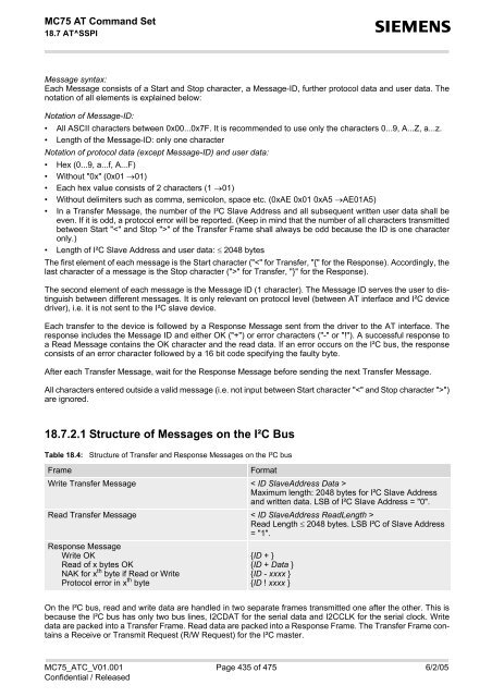
- Page 433: MC75 AT Command Set 18.7 AT^SSPI s
- Page 437 and 438: MC75 AT Command Set 18.7 AT^SSPI s
- Page 439 and 440: MC75 AT Command Set 19.2 ATS3 s 19.
- Page 441 and 442: MC75 AT Command Set 19.4 ATS5 s 19.
- Page 443 and 444: MC75 AT Command Set 20. Appendix s
- Page 445 and 446: MC75 AT Command Set 20.2 Star-Hash
- Page 447 and 448: MC75 AT Command Set 20.3 Available
- Page 449 and 450: MC75 AT Command Set 20.3 Available
- Page 451 and 452: MC75 AT Command Set 20.3 Available
- Page 453 and 454: MC75 AT Command Set 20.3 Available
- Page 455 and 456: MC75 AT Command Set 20.4 Availabili
- Page 457 and 458: MC75 AT Command Set 20.4 Availabili
- Page 459 and 460: MC75 AT Command Set 20.4 Availabili
- Page 461 and 462: MC75 AT Command Set 20.5 AT Command
- Page 463 and 464: MC75 AT Command Set 20.5 AT Command
- Page 465 and 466: MC75 AT Command Set 20.6 Factory De
- Page 467 and 468: MC75 AT Command Set 20.7 Summary of
- Page 469 and 470: MC75 AT Command Set 20.8 AT Command
- Page 471 and 472: MC75 AT Command Set 20.9 Alphabetic
- Page 473 and 474: MC75 AT Command Set 20.9 Alphabetic
- Page 475: MC75 AT Command Set 20.9 Alphabetic