Rotorcraft Flying Handbook, FAA-H-8083-21
Rotorcraft Flying Handbook, FAA-H-8083-21
Rotorcraft Flying Handbook, FAA-H-8083-21

You also want an ePaper? Increase the reach of your titles
YUMPU automatically turns print PDFs into web optimized ePapers that Google loves.
than zero, depending on the wind speed and direction.<br />
As you begin your takeoff, make sure the airspeed indicator<br />
is increasing at an appropriate rate. Keep in mind,<br />
however, that the airspeed indication might be unreliable<br />
below a certain airspeed due to rotor downwash.<br />
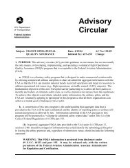
ALTIMETER<br />
The altimeter displays altitude in feet by sensing pressure<br />
changes in the atmosphere. There is an adjustable<br />
barometric scale to compensate for changes in atmospheric<br />
pressure. [Figure 12-3]<br />
VERTICAL SPEED INDICATOR<br />
The vertical speed indicator (VSI) displays the rate of<br />
climb or descent in feet per minute (f.p.m.) by measuring<br />
how fast the ambient air pressure increases or<br />
decreases as the helicopter changes altitude. Since the<br />
VSI measures only the rate at which air pressure<br />
changes, air temperature has no effect on this instrument.<br />
[Figure 12-4]<br />
Diaphragm<br />
Aneroid<br />
Wafers<br />
Altitude<br />
Indication<br />
Scale<br />
100 ft Pointer<br />
Altimeter<br />
Setting Window<br />
10,000 ft<br />
Pointer<br />
1,000 ft<br />
Pointer<br />
Static Port<br />
Altimeter Setting<br />
Adjustment Knob<br />
Crosshatch<br />
Flag<br />
A crosshatched<br />
area appears<br />
on some altimeters<br />
when displaying<br />
an altitude below<br />
10,000 feet MSL.<br />
Figure 12-3. The main component of the altimeter is a stack of<br />
sealed aneroid wafers. They expand and contract as atmospheric<br />
pressure from the static source changes. The mechanical<br />
linkage translates these changes into pointer movements on<br />
the indicator.<br />
The basis for altimeter calibration is the International<br />
Standard Atmosphere (ISA), where pressure, temperature,<br />
and lapse rates have standard values. However,<br />
actual atmospheric conditions seldom match the standard<br />
values. In addition, local pressure readings within<br />
a given area normally change over a period of time, and<br />
pressure frequently changes as you fly from one area to<br />
another. As a result, altimeter indications are subject to<br />
errors, the extent of which depends on how much the<br />
pressure, temperature, and lapse rates deviate from standard,<br />
as well as how recently you have set the altimeter.<br />
The best way to minimize altimeter errors is to update<br />
the altimeter setting frequently. In most cases, use the<br />
current altimeter setting of the nearest reporting station<br />
along your route of flight per regulatory requirements.<br />
INSTRUMENT CHECK—During the preflight, ensure<br />
that the static ports are unobstructed. Before lift-off, set<br />
the altimeter to the current setting. If the altimeter indicates<br />
within 75 feet of the actual elevation, the altimeter<br />
is generally considered acceptable for use.<br />
Calibrated<br />
Leak<br />
Direct Static<br />
Pressure<br />
Figure 12-4. Although the sealed case and diaphragm are<br />
both connected to the static port, the air inside the case is<br />
restricted through a calibrated leak. When the pressures are<br />
equal, the needle reads zero. As you climb or descend, the<br />
pressure inside the diaphragm instantly changes, and the<br />
needle registers a change in vertical direction. When the<br />
pressure differential stabilizes at a definite ratio, the needle<br />
registers the rate of altitude change.<br />
There is a lag associated with the reading on the VSI,<br />
and it may take a few seconds to stabilize when showing<br />
rate of climb or descent. Rough control technique<br />
and turbulence can further extend the lag period and<br />
cause erratic and unstable rate indications. Some aircraft<br />
are equipped with an instantaneous vertical speed<br />
indicator (IVSI), which incorporates accelerometers to<br />
compensate for the lag found in the typical VSI.<br />
INSTRUMENT CHECK—During the preflight, ensure<br />
that the static ports are unobstructed. Check to see that<br />
the VSI is indicating zero before lift-off. During takeoff,<br />
check for a positive rate of climb indication.<br />
SYSTEM ERRORS<br />
The pitot-static system and associated instruments are<br />
usually very reliable. Errors are generally caused when<br />
the pitot or static openings are blocked. This may be<br />
caused by dirt, ice formation, or insects. Check the pitot<br />
and static openings for obstructions during the preflight.<br />
It is also advisable to place covers on the pitot and static<br />
ports when the helicopter is parked on the ground.<br />
The airspeed indicator is the only instrument affected by a<br />
blocked pitot tube. The system can become clogged in two<br />
12-2