Rotorcraft Flying Handbook, FAA-H-8083-21
Rotorcraft Flying Handbook, FAA-H-8083-21
Rotorcraft Flying Handbook, FAA-H-8083-21

Create successful ePaper yourself
Turn your PDF publications into a flip-book with our unique Google optimized e-Paper software.
outing air across a heat source, such as an exhaust<br />
manifold, before it enters the carburetor. [Figure 5-11].<br />
Filter<br />
To Carb<br />
Helicopters have either a 14- or 28-volt, direct-current<br />
electrical system. On small, piston powered<br />
helicopters, electrical energy is supplied by an enginedriven<br />
alternator. These alternators have advantages<br />
over older style generators as they are lighter in<br />
weight, require lower maintenance, and maintain a<br />
uniform electrical output even at low engine r.p.m.<br />
[Figure 5-12]<br />
Door<br />
Carb Heat Off<br />
Filter<br />
To Carb<br />
Carb Heat<br />
Collector<br />
Manifold<br />
Pipe<br />
Avionic<br />
Bus<br />
(Optional Avionics)<br />
Avionics Relay<br />
Avionic<br />
Bus<br />
Bar<br />
Door<br />
Heated Air<br />
Carb Heat On<br />
Carb Heat<br />
Collector<br />
Manifold<br />
Pipe<br />
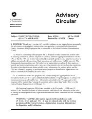
Figure 5-11. When you turn the carburetor heat ON, normal<br />
air flow is blocked, and heated air from an alternate source<br />
flows through the filter to the carburetor.<br />
FUEL INJECTION<br />
In a fuel injection system, fuel and air are metered at<br />
the fuel control unit but are not mixed. The fuel is<br />
injected directly into the intake port of the cylinder<br />
where it is mixed with the air just before entering the<br />
cylinder. This system ensures a more even fuel distribution<br />
in the cylinders and better vaporization, which<br />
in turn, promotes more efficient use of fuel. Also, the<br />
fuel injection system eliminates the problem of carburetor<br />
icing and the need for a carburetor heat system.<br />
TURBINE ENGINES<br />
The fuel control system on the turbine engine is fairly<br />
complex, as it monitors and adjusts many different<br />
parameters on the engine. These adjustments are done<br />
automatically and no action is required of the pilot<br />
other than starting and shutting down. No mixture<br />
adjustment is necessary, and operation is fairly simple<br />
as far as the pilot is concerned. New generation fuel<br />
controls incorporate the use of a full authority digital<br />
engine control (FADEC) computer to control the<br />
engine’s fuel requirements. The FADEC systems<br />
increase efficiency, reduce engine wear, and also<br />
reduce pilot workload. The FADEC usually incorporates<br />
back-up systems in the event of computer failure.<br />
ELECTRICAL SYSTEMS<br />
The electrical systems, in most helicopters, reflect the<br />
increased use of sophisticated avionics and other electrical<br />
accessories. More and more operations in today’s<br />
flight environment are dependent on the aircraft’s electrical<br />
system; however, all helicopters can be safely<br />
flown without any electrical power in the event of an<br />
electrical malfunction or emergency.<br />
Mag Switch<br />
G<br />
Off<br />
L<br />
R<br />
Both<br />
– +<br />
24V<br />
Battery<br />
Battery<br />
Switch<br />
R<br />
L<br />
Battery<br />
Relay<br />
Starting<br />
Vibrator<br />
Ret<br />
Adv<br />
Adv<br />
Starter<br />
Relay<br />
Clutch Actuator<br />
(Internal Limit Switches<br />
Shown in Full<br />
Disengage Position)<br />
On<br />
Off<br />
Avionics Master<br />
Switch<br />
Left<br />
Magneto<br />
Right<br />
Magneto<br />
Engine<br />
Starter<br />
Starter Release<br />
Switch<br />
Hold<br />
M/R Gearbox<br />
Press Switch<br />
Engage<br />
Clutch<br />
Switch<br />
Alternator<br />
–<br />
+<br />
Ammeter<br />
Alternator<br />
Control Unit<br />
Lights<br />
Panel<br />
Position<br />
Beacon<br />
Trim<br />
Instr<br />
Lndg Lt<br />
Radio<br />
Xpdr<br />
Clutch<br />
Turbine powered helicopters use a starter/generator<br />
system. The starter/generator is permanently coupled<br />
to the engine gearbox. When starting the engine, electrical<br />
power from the battery is supplied to the<br />
starter/generator, which turns the engine over. Once the<br />
engine is running, the starter/generator is driven by the<br />
engine and is then used as a generator.<br />
Current from the alternator or generator is delivered<br />
through a voltage regulator to a bus bar. The voltage<br />
regulator maintains the constant voltage required by<br />
the electrical system by regulating the output of the<br />
alternator or generator. An over-voltage control may be<br />
F2<br />
F1<br />
Bus Bar<br />
Alternator<br />
Switch<br />
Figure 5-12. An electrical system scematic like this sample is<br />
included in most POHs. Notice that the various bus bar<br />
accessories are protected by circuit breakers. However, you<br />
should still make sure all electrical equipment is turned off<br />
before you start the engine. This protects sensitive components,<br />
particularly the radios, from damage which may be<br />
caused by random voltages generated during the starting<br />
process.<br />
5-8