Rotorcraft Flying Handbook, FAA-H-8083-21
Rotorcraft Flying Handbook, FAA-H-8083-21
Rotorcraft Flying Handbook, FAA-H-8083-21

Create successful ePaper yourself
Turn your PDF publications into a flip-book with our unique Google optimized e-Paper software.
CORRELATOR / GOVERNOR<br />
A correlator is a mechanical connection between the<br />
collective lever and the engine throttle. When the collective<br />
lever is raised, power is automatically increased<br />
and when lowered, power is decreased. This system<br />
maintains r.p.m. close to the desired value, but still<br />
requires adjustment of the throttle for fine tuning.<br />
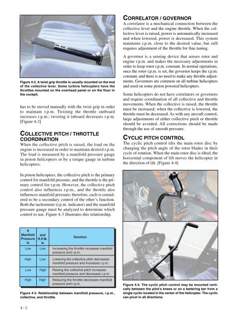
Figure 4-2. A twist grip throttle is usually mounted on the end<br />
of the collective lever. Some turbine helicopters have the<br />
throttles mounted on the overhead panel or on the floor in<br />
the cockpit.<br />
has to be moved manually with the twist grip in order<br />
to maintain r.p.m. Twisting the throttle outboard<br />
increases r.p.m.; twisting it inboard decreases r.p.m.<br />
[Figure 4-2]<br />
COLLECTIVE PITCH / THROTTLE<br />
COORDINATION<br />
When the collective pitch is raised, the load on the<br />
engine is increased in order to maintain desired r.p.m.<br />
The load is measured by a manifold pressure gauge<br />
in piston helicopters or by a torque gauge in turbine<br />
helicopters.<br />
A governor is a sensing device that senses rotor and<br />
engine r.p.m. and makes the necessary adjustments in<br />
order to keep rotor r.p.m. constant. In normal operations,<br />
once the rotor r.p.m. is set, the governor keeps the r.p.m.<br />
constant, and there is no need to make any throttle adjustments.<br />
Governors are common on all turbine helicopters<br />
and used on some piston powered helicopters.<br />
Some helicopters do not have correlators or governors<br />
and require coordination of all collective and throttle<br />
movements. When the collective is raised, the throttle<br />
must be increased; when the collective is lowered, the<br />
throttle must be decreased. As with any aircraft control,<br />
large adjustments of either collective pitch or throttle<br />
should be avoided. All corrections should be made<br />
through the use of smooth pressure.<br />
CYCLIC PITCH CONTROL<br />
The cyclic pitch control tilts the main rotor disc by<br />
changing the pitch angle of the rotor blades in their<br />
cycle of rotation. When the main rotor disc is tilted, the<br />
horizontal component of lift moves the helicopter in<br />
the direction of tilt. [Figure 4-4]<br />
In piston helicopters, the collective pitch is the primary<br />
control for manifold pressure, and the throttle is the primary<br />
control for r.p.m. However, the collective pitch<br />
control also influences r.p.m., and the throttle also<br />
influences manifold pressure; therefore, each is considered<br />
to be a secondary control of the other’s function.<br />
Both the tachometer (r.p.m. indicator) and the manifold<br />
pressure gauge must be analyzed to determine which<br />
control to use. Figure 4-3 illustrates this relationship.<br />
If<br />
Manifold<br />
Pressure<br />
is<br />
Low<br />
and<br />
R.P.M.<br />
is<br />
Low<br />
Solution<br />
Increasing the throttle increases manifold<br />
pressure and r.p.m.<br />
High<br />
Low<br />
Lowering the collective pitch decreases<br />
manifold pressure and increases r.p.m.<br />
Low<br />
High<br />
High<br />
High<br />
Raising the collective pitch increases<br />
manifold pressure and decreases r.p.m.<br />
Reducing the throttle decreases manifold<br />
pressure and r.p.m.<br />
Figure 4-3. Relationship between manifold pressure, r.p.m.,<br />
collective, and throttle.<br />
Figure 4-4. The cyclic pitch control may be mounted vertically<br />
between the pilot’s knees or on a teetering bar from a<br />
single cyclic located in the center of the helicopter. The cyclic<br />
can pivot in all directions.<br />
4-2