Rotorcraft Flying Handbook, FAA-H-8083-21
Rotorcraft Flying Handbook, FAA-H-8083-21
Rotorcraft Flying Handbook, FAA-H-8083-21

Create successful ePaper yourself
Turn your PDF publications into a flip-book with our unique Google optimized e-Paper software.
Resultant<br />
Lift<br />
Lift<br />
Resultant<br />
Thrust<br />
Rotor<br />
Drag<br />
Thrust<br />
Fuselage<br />
Drag<br />
Drag<br />
Weight<br />
Resultant<br />
Resultant<br />
Weight<br />
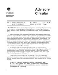
Figure 16-7. Unlike a helicopter, in forward powered flight the resultant rotor force of a gyroplane acts in a rearward direction.<br />
thrust directly from the engine through a propeller.<br />
[Figure 16-7]<br />
The force produced by the gyroplane rotor may be<br />
divided into two components; rotor lift and rotor drag.<br />
The component of rotor force perpendicular to the<br />
flight path is rotor lift, and the component of rotor force<br />
parallel to the flight path is rotor drag. To derive the<br />
total aircraft drag reaction, you must also add the drag<br />
of the fuselage to that of the rotor.<br />
ROTOR LIFT<br />
Rotor lift can most easily be visualized as the lift<br />
required to support the weight of the aircraft. When an<br />
airfoil produces lift, induced drag is produced. The<br />
most efficient angle of attack for a given airfoil produces<br />
the most lift for the least drag. However, the airfoil<br />
of a rotor blade does not operate at this efficient<br />
angle throughout the many changes that occur in each<br />
revolution. Also, the rotor system must remain in the<br />
autorotative (low) pitch range to continue turning in<br />
order to generate lift.<br />
Some gyroplanes use small wings for creating lift when<br />
operating at higher cruise speeds. The lift provided by<br />
the wings can either supplement or entirely replace<br />
rotor lift while creating much less induced drag.<br />
ROTOR DRAG<br />
Total rotor drag is the summation of all the drag forces<br />
acting on the airfoil at each blade position. Each blade<br />
position contributes to the total drag according to the<br />
speed and angle of the airfoil at that position. As the<br />
rotor blades turn, rapid changes occur on the airfoils<br />
depending on position, rotor speed, and aircraft speed.<br />
A change in the angle of attack of the rotor disc can<br />
effect a rapid and substantial change in total rotor drag.<br />
Rotor drag can be divided into components of induced<br />
drag and profile drag. The induced drag is a product of<br />
lift, while the profile drag is a function of rotor r.p.m.<br />
Because induced drag is a result of the rotor providing<br />
lift, profile drag can be considered the drag of the rotor<br />
when it is not producing lift. To visualize profile drag,<br />
consider the drag that must be overcome to prerotate<br />
the rotor system to flight r.p.m. while the blades are<br />
producing no lift. This can be achieved with a rotor system<br />
having a symmetrical airfoil and a pitch change<br />
capability by setting the blades to a 0° angle of attack.<br />
A rotor system with an asymmetrical airfoil and a built<br />
in pitch angle, which includes most amateur-built<br />
teeter-head rotor systems, cannot be prerotated without<br />
having to overcome the induced drag created as well.<br />
THRUST<br />
Thrust in a gyroplane is defined as the component of<br />
total propeller force parallel to the relative wind. As<br />
with any force applied to an aircraft, thrust acts around<br />
the center of gravity. Based upon where the thrust is<br />
applied in relation to the aircraft center of gravity, a relatively<br />
small component may be perpendicular to the<br />
relative wind and can be considered to be additive to<br />
lift or weight.<br />
In flight, the fuselage of a gyroplane essentially acts as<br />
a plumb suspended from the rotor, and as such, it is<br />
16-4