Rotorcraft Flying Handbook, FAA-H-8083-21
Rotorcraft Flying Handbook, FAA-H-8083-21
Rotorcraft Flying Handbook, FAA-H-8083-21

Create successful ePaper yourself
Turn your PDF publications into a flip-book with our unique Google optimized e-Paper software.
percent of the radius. In the driven region, part A of figure<br />
3-22, the total aerodynamic force acts behind the<br />
axis of rotation, resulting in a overall drag force. The<br />
driven region produces some lift, but that lift is offset<br />
by drag. The overall result is a deceleration in the rotation<br />
of the blade. The size of this region varies with the<br />
blade pitch, rate of descent, and rotor r.p.m. When<br />
changing autorotative r.p.m., blade pitch, or rate of<br />
descent, the size of the driven region in relation to the<br />
other regions also changes.<br />
There are two points of equilibrium on the blade—one<br />
between the driven region and the driving region, and<br />
one between the driving region and the stall region. At<br />
points of equilibrium, total aerodynamic force is<br />
aligned with the axis of rotation. Lift and drag are produced,<br />
but the total effect produces neither acceleration<br />
nor deceleration.<br />
The driving region, or autorotative region, normally<br />
lies between 25 to 70 percent of the blade radius. Part<br />
C of figure 3-22 shows the driving region of the blade,<br />
which produces the forces needed to turn the blades<br />
during autorotation. Total aerodynamic force in the<br />
driving region is inclined slightly forward of the axis of<br />
rotation, producing a continual acceleration force. This<br />
inclination supplies thrust, which tends to accelerate<br />
the rotation of the blade. Driving region size varies<br />
with blade pitch setting, rate of descent, and rotor r.p.m.<br />
By controlling the size of this region you can adjust<br />
autorotative r.p.m. For example, if the collective pitch<br />
is raised, the pitch angle increases in all regions. This<br />
causes the point of equilibrium to move inboard along<br />
the blade’s span, thus increasing the size of the driven<br />
region. The stall region also becomes larger while the<br />
driving region becomes smaller. Reducing the size of<br />
the driving region causes the acceleration force of the<br />
driving region and r.p.m. to decrease.<br />
The inner 25 percent of the rotor blade is referred to as<br />
the stall region and operates above its maximum angle<br />
of attack (stall angle) causing drag which tends to slow<br />
rotation of the blade. Part E of figure 3-22 depicts the<br />
stall region.<br />
A constant rotor r.p.m. is achieved by adjusting the collective<br />
pitch so blade acceleration forces from the driving<br />
region are balanced with the deceleration forces<br />
from the driven and stall regions.<br />
AUTOROTATION (FORWARD FLIGHT)<br />
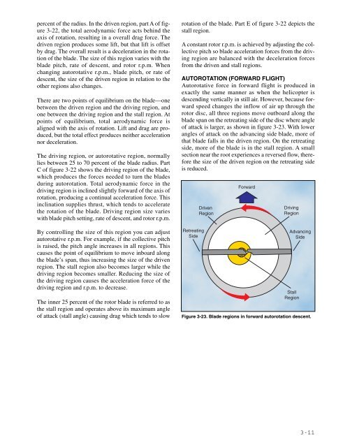
Autorotative force in forward flight is produced in<br />
exactly the same manner as when the helicopter is<br />
descending vertically in still air. However, because forward<br />
speed changes the inflow of air up through the<br />
rotor disc, all three regions move outboard along the<br />
blade span on the retreating side of the disc where angle<br />
of attack is larger, as shown in figure 3-23. With lower<br />
angles of attack on the advancing side blade, more of<br />
that blade falls in the driven region. On the retreating<br />
side, more of the blade is in the stall region. A small<br />
section near the root experiences a reversed flow, therefore<br />
the size of the driven region on the retreating side<br />
is reduced.<br />
Retreating<br />
Side<br />
Driven<br />
Region<br />
Forward<br />
Driving<br />
Region<br />
Advancing<br />
Side<br />
Stall<br />
Region<br />
Figure 3-23. Blade regions in forward autorotation descent.<br />
3-11