Rotorcraft Flying Handbook, FAA-H-8083-21
Rotorcraft Flying Handbook, FAA-H-8083-21
Rotorcraft Flying Handbook, FAA-H-8083-21

Create successful ePaper yourself
Turn your PDF publications into a flip-book with our unique Google optimized e-Paper software.
AUTOROTATIONS<br />
Both straight-ahead and turning autorotations should<br />
be practiced by reference to instruments. This training<br />
will ensure that you can take prompt corrective action<br />
to maintain positive aircraft control in the event of an<br />
engine failure.<br />
To enter autorotation, reduce collective pitch smoothly<br />
to maintain a safe rotor r.p.m. and apply pedal trim to<br />
keep the ball of the turn-and-slip indicator centered.<br />
The pitch attitude of the helicopter should be approximately<br />
level as shown by the attitude indicator. The<br />
airspeed indicator is the primary pitch instrument and<br />
should be adjusted to the recommended autorotation<br />
speed. The heading indicator is primary for bank in a<br />
straight-ahead autorotation. In a turning autorotation, a<br />
standard rate turn should be maintained by reference to<br />
the needle of the turn-and-slip indicator.<br />
COMMON ERRORS DURING AUTOROTATIONS<br />
1. Uncoordinated entry due to improper pedal trim.<br />
2. Poor airspeed control due to improper pitch attitude.<br />
3. Poor heading control in straight-ahead autorotations.<br />
4. Failure to maintain proper rotor r.p.m.<br />
5. Failure to maintain a standard rate turn during turning<br />
autorotations.<br />
SERVO FAILURE<br />
Most helicopters certified for single-pilot IFR flight are<br />
required to have autopilots, which greatly reduces pilot<br />
workload. If an autopilot servo fails, however, you<br />
have to resume manual control of the helicopter. How<br />
much your workload increases, depends on which<br />
servo fails. If a cyclic servo fails, you may want to land<br />
immediately as the workload increases tremendously.<br />
If an antitorque or collective servo fails, you might be<br />
able to continue to the next suitable landing site.<br />
INSTRUMENT TAKEOFF<br />
This maneuver should only be performed as part of<br />
your training for an instrument rating. The procedures<br />
and techniques described here should be modified, as<br />
necessary, to conform with those set forth in the operating<br />
instructions for the particular helicopter being<br />
flown.<br />
Adjust the miniature aircraft in the attitude indicator,<br />
as appropriate, for the aircraft being flown. After the<br />
helicopter is aligned with the runway or takeoff pad, to<br />
prevent forward movement of a helicopter equipped<br />
with a wheel-type landing gear, set the parking brake<br />
or apply the toe brakes. If the parking brake is used, it<br />
must be unlocked after the takeoff has been completed.<br />
Apply sufficient friction to the collective pitch control to<br />
minimize overcontrolling and to prevent creeping.<br />
Excessive friction should be avoided since this limits<br />
collective pitch movement.<br />
After checking all instruments for proper indications,<br />
start the takeoff by applying collective pitch and a predetermined<br />
power setting. Add power smoothly and<br />
steadily to gain airspeed and altitude simultaneously and<br />
to prevent settling to the ground. As power is applied and<br />
the helicopter becomes airborne, use the antitorque pedals<br />
initially to maintain the desired heading. At the same<br />
time, apply forward cyclic to begin accelerating to<br />
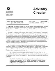
climbing airspeed. During the initial acceleration, the<br />
pitch attitude of the helicopter, as read on the attitude<br />
indicator, should be one to two bar widths low. The primary<br />
and supporting instruments after becoming airborne<br />
are illustrated in figure 12-22. As the airspeed increases<br />
50 60 70 80<br />
40 TORQUE 90<br />
30<br />
100<br />
20 PERCENT<br />
110<br />
10<br />
0<br />
120<br />
Supporting Pitch<br />
Primary Pitch<br />
Supporting Bank<br />
Supporting Pitch<br />
Primary<br />
Power<br />
Supporting Bank<br />
Primary Bank<br />
Supporting Pitch<br />
Figure 12-22. Flight instrument indications during an instrument takeoff.<br />
12-19