Rotorcraft Flying Handbook, FAA-H-8083-21
Rotorcraft Flying Handbook, FAA-H-8083-21
Rotorcraft Flying Handbook, FAA-H-8083-21

Create successful ePaper yourself
Turn your PDF publications into a flip-book with our unique Google optimized e-Paper software.
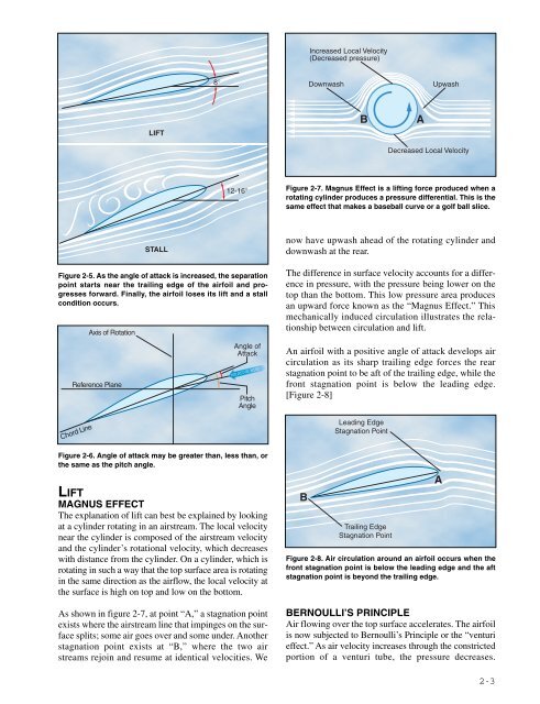
Increased Local Velocity<br />
(Decreased pressure)<br />
8°<br />
Downwash<br />
Upwash<br />
LIFT<br />
B<br />
A<br />
Decreased Local Velocity<br />
12-16° Figure 2-7. Magnus Effect is a lifting force produced when a<br />
rotating cylinder produces a pressure differential. This is the<br />
same effect that makes a baseball curve or a golf ball slice.<br />
Axis of Rotation<br />
Reference Plane<br />
STALL<br />
Figure 2-5. As the angle of attack is increased, the separation<br />
point starts near the trailing edge of the airfoil and progresses<br />
forward. Finally, the airfoil loses its lift and a stall<br />
condition occurs.<br />
Angle of<br />
Attack<br />
RELATIVE WIND<br />
Pitch<br />
Angle<br />
now have upwash ahead of the rotating cylinder and<br />
downwash at the rear.<br />
The difference in surface velocity accounts for a difference<br />
in pressure, with the pressure being lower on the<br />
top than the bottom. This low pressure area produces<br />
an upward force known as the “Magnus Effect.” This<br />
mechanically induced circulation illustrates the relationship<br />
between circulation and lift.<br />
An airfoil with a positive angle of attack develops air<br />
circulation as its sharp trailing edge forces the rear<br />
stagnation point to be aft of the trailing edge, while the<br />
front stagnation point is below the leading edge.<br />
[Figure 2-8]<br />
Chord Line<br />
Leading Edge<br />
Stagnation Point<br />
Figure 2-6. Angle of attack may be greater than, less than, or<br />
the same as the pitch angle.<br />
LIFT<br />
MAGNUS EFFECT<br />
The explanation of lift can best be explained by looking<br />
at a cylinder rotating in an airstream. The local velocity<br />
near the cylinder is composed of the airstream velocity<br />
and the cylinder’s rotational velocity, which decreases<br />
with distance from the cylinder. On a cylinder, which is<br />
rotating in such a way that the top surface area is rotating<br />
in the same direction as the airflow, the local velocity at<br />
the surface is high on top and low on the bottom.<br />
As shown in figure 2-7, at point “A,” a stagnation point<br />
exists where the airstream line that impinges on the surface<br />
splits; some air goes over and some under. Another<br />
stagnation point exists at “B,” where the two air<br />
streams rejoin and resume at identical velocities. We<br />
B<br />
Trailing Edge<br />
Stagnation Point<br />
A<br />
Figure 2-8. Air circulation around an airfoil occurs when the<br />
front stagnation point is below the leading edge and the aft<br />
stagnation point is beyond the trailing edge.<br />
BERNOULLI’S PRINCIPLE<br />
Air flowing over the top surface accelerates. The airfoil<br />
is now subjected to Bernoulli’s Principle or the “venturi<br />
effect.” As air velocity increases through the constricted<br />
portion of a venturi tube, the pressure decreases.<br />
2-3