Rotorcraft Flying Handbook, FAA-H-8083-21
Rotorcraft Flying Handbook, FAA-H-8083-21
Rotorcraft Flying Handbook, FAA-H-8083-21

Create successful ePaper yourself
Turn your PDF publications into a flip-book with our unique Google optimized e-Paper software.
swash plate and the rotating swash plate. [Figure 5-8]<br />
The stationary swash plate is mounted around the main<br />
rotor mast and connected to the cyclic and collective<br />
controls by a series of pushrods. It is restrained from<br />
rotating but is able to tilt in all directions and move vertically.<br />
The rotating swash plate is mounted to the stationary<br />
swash plate by means of a bearing and is<br />
allowed to rotate with the main rotor mast. Both swash<br />
plates tilt and slide up and down as one unit. The rotating<br />
swash plate is connected to the pitch horns by the<br />
pitch links.<br />
Low Level<br />
Warning<br />
Light<br />
Fuel<br />
Shutoff<br />
Mixture<br />
Control<br />
Primer<br />
Fuel Quantity<br />
Gauge<br />
Tank<br />
Vent<br />
Stationary<br />
Swash<br />
Plate<br />
Pitch<br />
Link<br />
Rotating<br />
Swash<br />
Plate<br />
Throttle<br />
Carburetor<br />
Primer Nozzle<br />
at Cylinder<br />
Shut-off<br />
Valve<br />
Control<br />
Rod<br />
Fuel<br />
Strainer<br />
Figure 5-8. Collective and cyclic control inputs are transmitted<br />
to the stationary swash plate by control rods causing it to<br />
tilt or to slide vertically. The pitch links attached from the<br />
rotating swash plate to the pitch horns on the rotor hub<br />
transmit these movements to the blades.<br />
FUEL SYSTEMS<br />
The fuel system in a helicopter is made up of two<br />
groups of components: the fuel supply system and the<br />
engine fuel control system.<br />
FUEL SUPPLY SYSTEM<br />
The supply system consists of a fuel tank or tanks, fuel<br />
quantity gauges, a shut-off valve, fuel filter, a fuel line<br />
to the engine, and possibly a primer and fuel pumps.<br />
[Figure 5-9]<br />
The fuel tanks are usually mounted to the airframe as<br />
close as possible to the center of gravity. This way, as<br />
fuel is burned off, there is a negligible effect on the center<br />
of gravity. A drain valve located on the bottom of<br />
the fuel tank allows the pilot to drain water and sediment<br />
that may have collected in the tank. A fuel vent<br />
prevents the formation of a vacuum in the tank, and an<br />
overflow drain allows for fuel to expand without rupturing<br />
the tank. A fuel quantity gauge located on the<br />
pilot’s instrument panel shows the amount of fuel<br />
measured by a sensing unit inside the tank. Some<br />
gauges show tank capacity in both gallons and pounds.<br />
The fuel travels from the fuel tank through a shut-off<br />
valve, which provides a means to completely stop fuel<br />
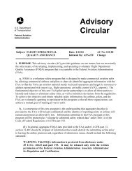
Figure 5-9. A typical gravity feed fuel system, in a helicopter<br />
with a reciprocating engine, contains the components<br />
shown here.<br />
flow to the engine in the event of an emergency or fire.<br />
The shut-off valve remains in the open position for all<br />
normal operations.<br />
Most non-gravity feed fuel systems contain both an<br />
electric pump and a mechanical engine driven pump.<br />
The electrical pump is used to maintain positive fuel<br />
pressure to the engine pump and also serves as a<br />
backup in the event of mechanical pump failure. The<br />
electrical pump is controlled by a switch in the cockpit.<br />
The engine driven pump is the primary pump that supplies<br />
fuel to the engine and operates any time the<br />
engine is running.<br />
A fuel filter removes moisture and other sediment from<br />
the fuel before it reaches the engine. These contaminants<br />
are usually heavier than fuel and settle to the bottom<br />
of the fuel filter sump where they can be drained<br />
out by the pilot.<br />
Some fuel systems contain a small hand-operated pump<br />
called a primer. A primer allows fuel to be pumped<br />
directly into the intake port of the cylinders prior to<br />
engine start. The primer is useful in cold weather when<br />
fuel in the carburetor is difficult to vaporize.<br />
ENGINE FUEL CONTROL SYSTEM<br />
The purpose of the fuel control system is to bring outside<br />
air into the engine, mix it with fuel in the proper<br />
proportion, and deliver it to the combustion chamber.<br />
5-6