Volume 2, Issue 1, 2011, Full Text - 5th International Conference on ...
Volume 2, Issue 1, 2011, Full Text - 5th International Conference on ...
Volume 2, Issue 1, 2011, Full Text - 5th International Conference on ...

Create successful ePaper yourself
Turn your PDF publications into a flip-book with our unique Google optimized e-Paper software.
Sustainable C<strong>on</strong>structi<strong>on</strong> and Design <str<strong>on</strong>g>2011</str<strong>on</strong>g><br />
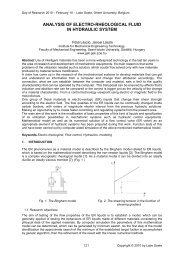
According to the relati<strong>on</strong> to be found in the literature the main cutting force is the functi<strong>on</strong> of the specific<br />
cutting force (or resistance) and of the chip area. As during measuring we have also measured the main<br />
cutting force, the chip area was given because of parameters set, so the value of the specific cutting force<br />
can be got by transposing the original relati<strong>on</strong>.<br />
F<br />
Fv<br />
⎡ N<br />
= k<br />
s<br />
⋅ A = k<br />
s<br />
⋅ a ⋅ s ⇒ k<br />
s<br />
= →<br />
⋅ ⎢ 2<br />
a s ⎣mm<br />
⎤<br />
⎥<br />
⎦<br />
v<br />
(1)<br />
The material tested and the cutting speed used occur in the title of sample diagram. Beside the depth of cut<br />
and feeding the specific cutting resistance (y-axis) in N/mm 2 unit can be found <strong>on</strong> the datum lines.<br />
3.2 Chip pictures (photographs)<br />
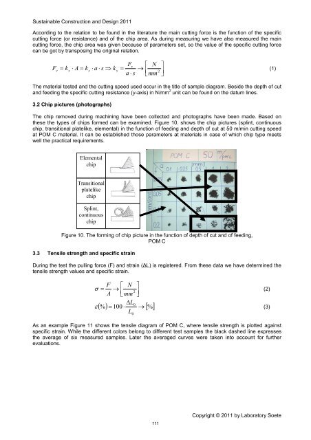
The chip removed during machining have been collected and photographs have been made. Based <strong>on</strong><br />
these the types of chips formed can be examined. Figure 10. shows the chip pictures (splint, c<strong>on</strong>tinuous<br />
chip, transiti<strong>on</strong>al platelike, elemental) in the functi<strong>on</strong> of feeding and depth of cut at 50 m/min cutting speed<br />
at POM C material. It can be established those parameters at materials in case of which chip type meets<br />
well the practical requirements.<br />
Elemental<br />
chip<br />
Transiti<strong>on</strong>al<br />
platelike<br />
chip<br />
Splint,<br />
c<strong>on</strong>tinuous<br />
chip<br />
Figure 10. The forming of chip picture in the functi<strong>on</strong> of depth of cut and of feeding,<br />
POM C<br />
3.3 Tensile strength and specific strain<br />
During the test the pulling force (F) and strain (ΔL) is registered. From these data we have determined the<br />
tensile strength values and specific strain.<br />
F ⎡ N<br />
→<br />
A ⎢<br />
⎣mm<br />
∆L<br />
% = 100 ⋅<br />
L<br />
=<br />
2<br />
⎤<br />
⎥<br />
⎦<br />
σ (2)<br />
( ) 0<br />
→ [%]<br />
ε (3)<br />
0<br />
As an example Figure 11 shows the tensile diagram of POM C, where tensile strength is plotted against<br />
specific strain. While the different colors bel<strong>on</strong>g to different test samples the black dashed line expresses<br />
the average of six measured samples. Later the averaged curves were taken into account for further<br />
evaluati<strong>on</strong>s.<br />
111<br />
Copyright © <str<strong>on</strong>g>2011</str<strong>on</strong>g> by Laboratory Soete