Volume 2, Issue 1, 2011, Full Text - 5th International Conference on ...
Volume 2, Issue 1, 2011, Full Text - 5th International Conference on ...
Volume 2, Issue 1, 2011, Full Text - 5th International Conference on ...

You also want an ePaper? Increase the reach of your titles
YUMPU automatically turns print PDFs into web optimized ePapers that Google loves.
Sustainable C<strong>on</strong>structi<strong>on</strong> and Design <str<strong>on</strong>g>2011</str<strong>on</strong>g><br />
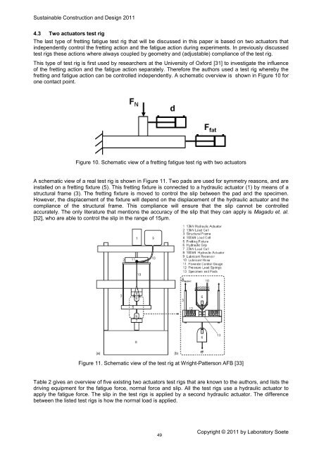
4.3 Two actuators test rig<br />
The last type of fretting fatigue test rig that will be discussed in this paper is based <strong>on</strong> two actuators that<br />
independently c<strong>on</strong>trol the fretting acti<strong>on</strong> and the fatigue acti<strong>on</strong> during experiments. In previously discussed<br />
test rigs these acti<strong>on</strong>s where always coupled by geometry and (adjustable) compliance of the test rig.<br />
This type of test rig is first used by researchers at the University of Oxford [31] to investigate the influence<br />
of the fretting acti<strong>on</strong> and the fatigue acti<strong>on</strong> separately. Therefore the authors used a test rig whereby the<br />
fretting and fatigue acti<strong>on</strong> can be c<strong>on</strong>trolled independently. A schematic overview is shown in Figure 10 for<br />
<strong>on</strong>e c<strong>on</strong>tact point.<br />
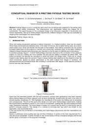
Figure 10. Schematic view of a fretting fatigue test rig with two actuators<br />
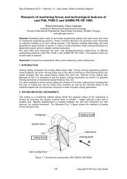
A schematic view of a real test rig is shown in Figure 11. Two pads are used for symmetry reas<strong>on</strong>s, and are<br />
installed <strong>on</strong> a fretting fixture (5). This fretting fixture is c<strong>on</strong>nected to a hydraulic actuator (1) by means of a<br />
structural frame (3). The fretting fixture is moved to c<strong>on</strong>trol the slip between the pad and the specimen.<br />
However, the displacement of the fixture will depend <strong>on</strong> the displacement of the hydraulic actuator and the<br />
compliance of the structural frame. This compliance will ensure that the slip cannot be c<strong>on</strong>trolled<br />
accurately. The <strong>on</strong>ly literature that menti<strong>on</strong>s the accuracy of the slip that they can apply is Magadu et. al.<br />
[32], who are able to c<strong>on</strong>trol the slip in the range of 15µm.<br />
Figure 11. Schematic view of the test rig at Wright-Patters<strong>on</strong> AFB [33]<br />
Table 2 gives an overview of five existing two actuators test rigs that are known to the authors, and lists the<br />
driving equipment for the fatigue force, normal force and slip. All the test rigs use a hydraulic actuator to<br />
apply the fatigue force. The slip in the test rigs is applied by a sec<strong>on</strong>d hydraulic actuator. The difference<br />
between the listed test rigs is how the normal load is applied.<br />
49<br />
Copyright © <str<strong>on</strong>g>2011</str<strong>on</strong>g> by Laboratory Soete