Volume 2, Issue 1, 2011, Full Text - 5th International Conference on ...
Volume 2, Issue 1, 2011, Full Text - 5th International Conference on ...
Volume 2, Issue 1, 2011, Full Text - 5th International Conference on ...

You also want an ePaper? Increase the reach of your titles
YUMPU automatically turns print PDFs into web optimized ePapers that Google loves.
Sustainable C<strong>on</strong>structi<strong>on</strong> and Design <str<strong>on</strong>g>2011</str<strong>on</strong>g><br />
3. CONTROL METHOD<br />
Designing the c<strong>on</strong>trol method we determined to apply two solenoid valves (<strong>on</strong>e for each chamber), the<br />
biggest benefit of which is that the number of c<strong>on</strong>trol signals is thus raised to the sec<strong>on</strong>d power.<br />
Number of<br />
variati<strong>on</strong><br />
Signal of<br />
solenoid<br />
valve 1<br />
Signal of<br />
solenoid<br />
valve 2<br />
Movement of the cylinder pist<strong>on</strong><br />
1 fill empty positive directi<strong>on</strong>, fast<br />
2 fill close positive directi<strong>on</strong>, slow<br />
3 fill fill immobile<br />
4 close empty positive directi<strong>on</strong>, unc<strong>on</strong>trolled<br />
5 close close first immobile, then unc<strong>on</strong>trolled<br />
6 close fill negative directi<strong>on</strong>, slow<br />
7 empty empty accidental directi<strong>on</strong>, unc<strong>on</strong>trolled<br />
8 empty close negative directi<strong>on</strong>, unc<strong>on</strong>trolled<br />
9 empty fill negative directi<strong>on</strong>, fast<br />
Table 2. Available variati<strong>on</strong>s using two solenoid valves<br />
Out of the variati<strong>on</strong>s presented in Table 2, we ignored the unc<strong>on</strong>trolled <strong>on</strong>es (where pressure in both<br />
chambers changes in an unc<strong>on</strong>trolled way) which thus leaves us with five useful solenoid valve variati<strong>on</strong>s.<br />
However, in order to stop the movement of the cylinder pist<strong>on</strong> in variati<strong>on</strong> number 3, a complementary<br />
element had to be introduced (due to the asymmetric c<strong>on</strong>structi<strong>on</strong> of the cylinder we used). Using a<br />
pressure regulator, the positive chamber was filled with supply pressure decreased in proporti<strong>on</strong> to the<br />
surfaces of the pist<strong>on</strong>. As a result a balance of force was reached based <strong>on</strong> equati<strong>on</strong> number (5).<br />
As a first step we started out from a graph representati<strong>on</strong>, where time and positi<strong>on</strong> were placed <strong>on</strong> the<br />
axes. This way the most important c<strong>on</strong>trol parameter, the error (difference between a measured process<br />
variable and a desired set-point) can be visualized easily if we represent both the ideal and the actual<br />
positi<strong>on</strong> values (reference signal and measured output respectively) plotted against the elapsed time.<br />
Based <strong>on</strong> the scale of the error we might form predicti<strong>on</strong>s as to which valve variati<strong>on</strong> has to be realized by<br />
the c<strong>on</strong>trol method in order to decrease the absolute value of the error.<br />
Number of c<strong>on</strong>trol<br />
signal<br />
Relati<strong>on</strong> between<br />
reference signal and<br />
measured output<br />
Desired pist<strong>on</strong><br />
movement<br />
Number of<br />
variati<strong>on</strong> in<br />
Table 2<br />
1 r >> y m positive directi<strong>on</strong>, fast 1<br />
2 r > y m positive directi<strong>on</strong>, slow 2<br />
3 r ≈ y m immobile 3<br />
4 r < y m negative directi<strong>on</strong>, slow 6<br />
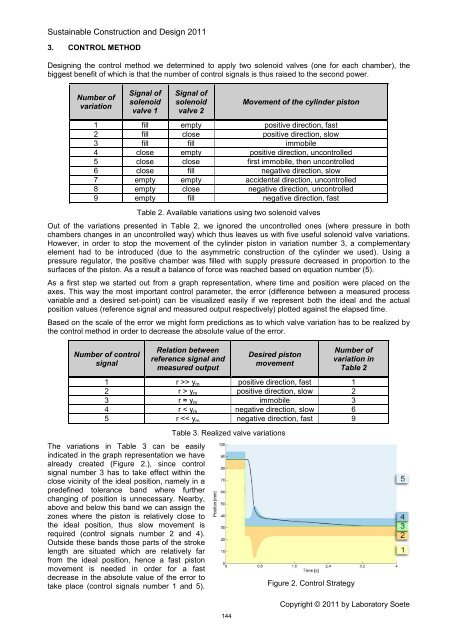
5 r