mitsubishi - Al Kossow's Bitsavers
mitsubishi - Al Kossow's Bitsavers
mitsubishi - Al Kossow's Bitsavers
Create successful ePaper yourself
Turn your PDF publications into a flip-book with our unique Google optimized e-Paper software.
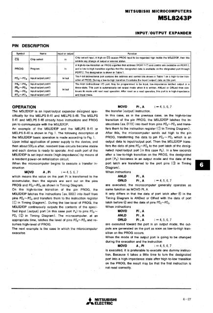
MITSUBISHI MICROCOMPUTERSMSL8243PINPUT/OUTPUT EXPANDERPIN DESCRIPTIONSymbol Name Input or output Function-Chip select input. A high on CS causes PROG input to be regarded high inside the M5L8243P, then thisCS Chip selectIninhibits any change of output or internal status.A high-to-Iow transition on PROG signifies that address (PORT 4-7) and control are. available on PORT 2,PROG Program In and a low-to-high transition signifies that the designated data is available on the disignated port throughPORT 2. The designation is shown in Table 1.P2 0 ........ P2 3 Input/output port 2 In/outThe 4-bit bidirectional port contains the address and control bits shown in Table 1 on a high-to-Iow transitionof PROG. During a low-to-high transition it contains the input (output) data on this port.P4o""""P4 3 Input/output port 4 The 4-bit bidirectional I/O port. May be programmed to be input, low-impedance latched output or aP5 0 ........ P5 3 Input/output port 5three-state. This port is automatically set output mode when it is written. AN Led or ORLed then con-In/outP66 ........ P63 Input/output port 6 tinues its mode until next read operation. After reset on a read operation, .this port is in high-impedanceP7o""""P7 3 Input/output port 7 and input mode.OPERATIONThe M5L8243P is an input/output expander designed specificallyfor the MELPS 8-41 and MELPS 8-48. The MELPS8-41 and MELPS 8-48 already have instructions and PROGpin to communicate with the M5L8243P.An example of the M5L8243P and the MELPS 8-41 orMELPS 8-48 is shown in Fig. 1. The following description ofthe M5L8243P basic operation is made according to Fig. 1.Upon initial application of power supply to the device, andthen about 500,us after, resident bias circuits become stableand each. device is ready to operate. And each port of theM5L8243P is set input mode (high-impedance) by means ofa resident power-on initialization circuit.When the microcomputer begins to execute a transfer instruction. MQVO A,Pi i = 4,5,6,7which means the value on the port Pi is transferred to theaccumulator, then the signals are sent out on the pinsPROG and P2o ........ P2 3 as shown in Timing Diagram.On the high-to-Iow transition of the pin PROG, theM5L8243P latches the instructions (ex. 0000) into itself frompins P2o ........ P2 3 and transfers them to the instruction register(CD in Timing Diagram). During the lOW-level of PROG, theM5L8243P continuously outputs the contents of the specifiedinput (output) port (in this case port P 4 ) to pins P2o""""P2 3 (~ in Timing Diagram). The microcomputer, at anappropriate time, latches the level of pins P2o"""" P2 3 and resumeshigh-level of PROG.The next example is the case in which the microcomputerexecutesMOVO Pi, A i = 4, 5, 6, 7the transfer (output) instruction.In this case, as in the previous case, on the high-to-Iowtransition of the pin PROG, the M5L8243P latches the instructions(ex. 0110) into itself from pins P2o"""" P2 3 and transfersthem to the instruction register (CD in Timing Diagram).After this, the microcomputer sends out high to the pinPROG, transferring the data to pin P2o """" P2 3 which is anoutput data to input/output port. Then the. M5L8243P transfersthe data of pins P2o ........ P2 3 to the port latch of the designatedinput/output port (in this case ps). In a few secondsafter a low-to-high transition on the PROG, the designatedport (ps) becomes in an output mode and the data of theport latch are transferred to the port pins (@ in TimingDiagram).When instructionsANlO Pi,AORlO Pi,A i = 4, 5, 6, 7are executed, the microcomputer generally operates assame function as MOVD Pi, A.It only differs in that the data of port latch after @ in theTiming Diagram is ANDed or ORed with the data of portlatch before @ and the data of pins P2o""""P2 3 .When instructionsMOVOANlOORlOPi,APi, APi ,A i = 4, 5, 6, 7are executed toward the port in an output mode, the outputsare generated on the port as soon as low-to-high transitionon the PROG occurs.When the mode of the output port is going to be changedduring the execution and the instructionMOVO A , Pi i = 4, 5, 6, 7is executed, it is preferable to execute one dummy instruction.Because it takes a little time to turn the designatedport into a high-impedance state after high-to-Iow transitionon the PROG, the result may be that the first instruction isnot read correctly.• MITSUBISHI.... ELECTRIC6-27


