

mitsubishi - Al Kossow's Bitsavers
mitsubishi - Al Kossow's Bitsavers
mitsubishi - Al Kossow's Bitsavers

You also want an ePaper? Increase the reach of your titles
YUMPU automatically turns print PDFs into web optimized ePapers that Google loves.
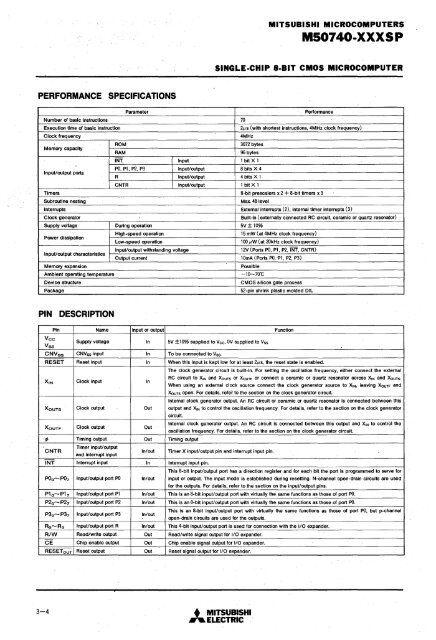
MITSUBISHI MICROCOMPUTERSMS0740-XXXS PSINGLE-CHIP a-BIT CMOS MICROCOMPUTERPERFORMANCE SPECIFICATIONSParameterPerformanceNumber of basic Instructions 70Execution time of basic Instruction2I-Ls (with shortest instructions, 4MHz clock frequency)Clock frequency4MHzROM3072 bytesMemory capacityRAM96 bytesINT Input 1 bit X 1Input/output portsPO, P1, P2, P3 Input/output 8 bits X 4R Input/output 4 bits XlCNTR Input/output 1 bitX1Timers B-bit pre scalers x 2 + 8-bit timers x 3Subroutine nestingMax. 48 levelInterrupts External interrupts (2), internal timer interrupts (3)Clock gen~ratorBuilt-in (externally connected RC circuit, ceramic or quartz resonator)Supply voltage During operation 5V± 10%Power dissipationInput/output characteristicsMemory expansionHigh-speed operation15 mW (at 4MHz clock frequency)Low-speed operation100 I-LW (at 20kHz clock frequency)Input/output withstanding voltage12V(Ports PO, pt, P2,INT, CNTR)Output current10mA (Ports PO, P1, P2, P3)PossibleAmbient operating temperature-10-70·CDevice structureCMOS silicon gate processPackage52-pin shrink plastic molded OILPIN DESCRIPTIONPin Name Input or outputVeeVssSupply voltageInCNVss CNVss Input InRESET Reset input InX 1N Clock input InX OUTS Clock output OutX OUTF Clock output Out¢> Timing output OutCNTRTimer input/outputand Interrupt inputIn/outINT Interrupt input InPO O -P07 Input/output port PO In/outP1 0 -P1 7 Input/output port P1 In/outP2 0 -P2 7 Input/output port P2 In/outP3t1-P37 Input/output port P3 In/outR o -R 3 Input/output port R In/outR/W Read/write output OutCE Chip enable output OutRESETouT Reset outputOut5V ±10% supplied to Vee, OV supplied to VssTo be connected to Vss.FunctionWhen this input is kept low for at least 2I-Ls, the reset state is enabled.The clock generator circuit Is built-In. For setting the oscillation frequency, either connect the externalRC circuit to X1N and XOUTS or XOUTF or connect a ceramic or quartz resonator across X1N and XOUTS.When using an external clock source connect the clock generator source to X1N, leaving XOUTF andXOUTS open. For details, refer to the section on the clock generator circuit.Internal clock generator output. An RC circuit or ceramic or quartz resonator is connected between thisoutput and X1N to control the oscillation frequency. For details, refer to the section on the clock generatorcircuit.Internal clock generator output. An RC circuit is connected between this output and XIN to control theoscillation frequency. For details, refer to the section on the clock generator circuit.Timing outputTimer X input/output pin and interrupt input pin.Interrupt input pin.This 8-bit input/output port has a direction register and for each bit the port is programmed to serve forinput or output. The input mode is established during resetting. N-channel open-drain circuits are usedfor the outputs. For details, refer to the section on the inpi,lt/output pins.This is an 8-blt input/output port with virtually the same functions as those of port PO.This is an 8-bit input/output port 'with virtually the same functions as those of port PO.This is an 8"bit input/output port with virtually the same functions as those of port PO, but p-channelopen-drain circuits are used for the outputs.This 4-bit input/output port is used for connection with the I/O expander.Read/write signal output for I/O expander.Chip enable Signal output for I/O expander.Reset signal output for I/O expander.3-4•. MITSUBISHI"ELECTRIC


