

mitsubishi - Al Kossow's Bitsavers
mitsubishi - Al Kossow's Bitsavers
mitsubishi - Al Kossow's Bitsavers

You also want an ePaper? Increase the reach of your titles
YUMPU automatically turns print PDFs into web optimized ePapers that Google loves.
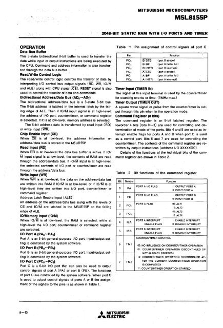
MITSUBISHI MICROCOMPUTERSMSL81SSP2048-BIT STATIC RAM WITH I/O PORTS AND TIMER; OPERATIONData Bus BufferThis 3-state bidirectional 8-bit buffer is used to transfer thedata while input or output instructions are being executed bythe CPU. Command and address information is also transferredthrough the data bus buffer.ReadlWrite Control LogicThe read/write control logic controls the transfer of data byinterpreting I/O' control bus output signals (RD, WR, 10iMand ALE) along with CPU signal (CE). RESET signal is alsoused to control the transfer of data and commands.Bidirectional Address/Data Bus (ADo-AD 7 )The bidirectional address/data bus is a 3-state 8-bit bus.The 8-bit address is latched in the internal latch by the failingedge of ALE. Then if 10iM input signal is at high-level,the address of I/O port, counter/timer, or command registeris selected. If it is at low-level, memory address is selected.The 8-bit address data is transferred by read input (RD)or write input (WR).Chip Enable Input (CE)When CE is at low-level, the address information onaddress/data bus is stored in the M5L8155PRe.d Input (RD)When RD is at low-level the data bus buffer is active. If 10/M input signal is at low-level, the contents of RAM are readthrough the address/data bus. If 10/M input is at high-level,the selected contents of I/O port or counter/timer are readthrough the address/data bus.Write Input (WR) ,When WR is at low-level, the data on the address/data busare written into RAM if 10/M is at low-level, or if 10/M is athigh-level they are written into I/O port, counter/timer orcommand register.Address Latch Enable Input (ALE)An address on the address/data bus along with the levels ofCE and IO/M are latched in the M5L8155P on the fallingedge of ALE.10lMemory Input (101M)When 10/M is at low-level, the RAM is selected, while athigh-level the I/O port, counter/timer or command registerare selected.1/0 Port A (PAo-PA t )Port A is an 8-bit general-purpose I/O port. Input/output set~ting is controlled by the syst~m software.1/0 Port B (PBo-PB 7 )Port B is an 8-bit general-purpose I/O port. Input/output settingis controlled by the system software.1/0 Port C (PC~-PC5)Port C is a 6-bit I/O port that can also be used to outputcontrol signals of port A (PA) or port B (PB). The functionsof port C are controlled by the system software: When port Cis used to output control signals of ports A or B the iissignmentof the siQnals to the pins is as shown in Table 1 .TablePin1 Pin assignment of control signals of, ,porteFunctionPCs B STB (port B strobe)PC4 B SF (port B buffer full)PC3 BINTR (port B interrupt)PC2 ASTB (port A strobe)PCl A BF (port A buffer full)PCa AINTR (port A interrupt) '-Timer Input (TIMER IN)The signal at this input terminal is used by the counter/timerfor counting events or time. (3MHz max.)Timer Output (TIMER OUT)A square wave signal or pulse from the counter/timer is outputthrough this pin when in the operation mode.Command Register (8 bits)The command register is an 8-bit latched register. Theloworder 4 bits (bits 0 ...... 3) are used for controlling and determinationof mode of the ports. Bits 4 and 5 are used as interruptenable flags for ports A and B when port C is usedas a control port. Bits 6 and 7 are used for controlling thecounter/timer. The contents of the command register are rewrittenby output instructions (address I/O XXXXXOOO).Details of the functions of the individual bits of the commandregister are shown in Table 2.Table2 Bit functions of the command registerBit Symbol Function0 PAIPB2 PCl3 PC24 lEA5 IEB6 TMI7 TM2PORT A I/O FLAGPORT B I/O FLAGPORT C FLAGPORT A ,INTERRUPTENABLE FLAGPORT B INTERRUPTENABLE FLAGCOUNTER/TIMER CONTROL1: OUTPUT PORT A0: INPUT PORT A1: OUTPUT PORT B0: INPUT PORT B00: ALTI11: ALT2'01: ALT310: ALT41: ENABLE INTERRUPT0: DISABLE INTERRUPT1: ENABLE INTERRUPT0: DISABLE INTERRUPT00: NO INFLUENCE ON COUNTER/TIMER OPERATION01: COUNTER/TIMER OPERATION DISCONTINUED (IFNOT ALREADY STOPPED)10: COUNTER/TIMER OPERATION DISCONTINUED AF-TER THE CURRENT COUNTER/TIMER 'OPERATIONIS COMPLETED11: COUNTER/TIMER OPERATION STARTED6-40 • ,MITSUBISHI'" ELECTRIC


