

mitsubishi - Al Kossow's Bitsavers
mitsubishi - Al Kossow's Bitsavers
mitsubishi - Al Kossow's Bitsavers

Create successful ePaper yourself
Turn your PDF publications into a flip-book with our unique Google optimized e-Paper software.
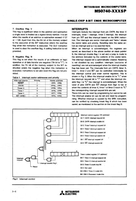
MITSUBISHI MICROCOMPUTERSMS0740·XXXSPSINGLE·CHIP 8·BIT CMOS MICROCOMPUTER7 .. Overflow Flag VThis flag is significant when in the addition and subtructiona single word is treated as a signed binary number. It is setwhen the results of an addition or subtraction exceed + 127or -128. Apart from this, the 6th bit of the memory subjectto the execution of the BIT instruction enters the overflowflag when this instruction is executed. The ClV instructionis used to clear the overflow flag. A setting instruction is notprovided.8. Negative Flag NThis flag is set when the results of an arithmetic or logicoperation or of data transfer are negative (7th bit is "1"). Inaddition, the 7th bit. of the memory subject to the BIT instructionenters the negative flag when this instruction isexecuted. Instructions to set and reset this flag are not provided.Table 1Interrupt sourceRESETCNTRTimer XTimer 1Timer 2INT (BRK)Interrupt vector addresses and priorityPriority123456Vector address1FFF, 1FFE1FFD, 1FFC1FFB, 1FFA1FF9, 1FF81FF7, 1FF61FF5, 1FF4INTERRUPTSInterrupts include the interrupt from pin CNTR, the timer Xinterrupts, timer 1 interrupt, timer 2 interrupt, the interruptfrom pin INT and the interrupt based on the BRK instruction.The interrupts are vector interrupts and Table 1 showsthe vector table and priority. Resetting take the same actionas interrupt and so it is descried here.When an interrupt is acknowledged, the registers aresaved, as described in the above section on stack pointerS, the interrupt disable flag I is set and a jump is made tothe address indicated by the contents of the vector table.The i,nterrupt request bit is automatically cleared. Resettingis not disabled by any condition. Interrupts (exclusive ofresetting) are not acknowledged when the interrupt disableflag has been set. The interrupts from pin CNTR, timer X,timer 1, timer 2 and INT can be controlled individually bythe interrupt control and timer control registers. This isshown in Fig. 3. When the interrupt enable bit is "1," whenthe interrupt request bit is "1" and when the interrupt disableflag I is "0," the interrupt is acknowledged. When thelevel of pins CNTR and INT change from high to low orwhen the contents of timer X, timer 1 or timer 2 reach to "0,"the corresponding interrupt request bits are set.These bits can be reset by programming but cannot be set.The interrupt enable bit can be set and reset by programming.Whether interrupt is caused by the BRK instruction,can be verified by checking break flag B which has beensaved, as mentioned in the section on the break flag B.Interrupt control register (FE address)Bit 7: CNTR interrupt request bitBit 6: CNTR interrupt enable bitBit 5: Timer 1 interrupt request bitBit 4: Timer 1 interrupt enable bitBit 3: Timer 2 interrupt request bitBit 2: Timer 2 interrupt enable bitBit 1: INT interrupt request bitBit 0: INT interrupt enable bitTimer control register (FF address)InterruptrequestBit 7: Timer X interrupt request bitBit 6: Timer X interrupt enable bitBit 5: Timer X count stop bitBit 4: Not usedBit 3JBit 2: Timer X mode bitsBit 1 JBit 0: Processor mode bitsFig.3Interrupt control3-8 • MITSUBISHI.... ELECTRIC


