- Page 6 and 7:
MITSUBISHI MICROCOMPUTERSCONTENTSDG
- Page 8:
GUIDANCE D
- Page 11 and 12:
MITSUBISHI MICROCOMPUTERSDEVELOPMEN
- Page 13 and 14:
MITSUBISHI MICROCOMPUTERSORDERING I
- Page 15 and 16:
MITSUBISHI MICROCOMPUTERSPACKAGE OU
- Page 17 and 18:
MITSUBISHI MICROCOMPUTERSLE,:lTER S
- Page 19 and 20:
MITSUBISHI MICROCOMPUTERSLETTER SYM
- Page 21 and 22:
MITSUBISHI MICROCOMPUTERSSYMBOLOGYN
- Page 23 and 24:
. MITSUBISHI MICROCO.MPUTERSQUALITY
- Page 25 and 26:
MITSUBISHI MICROCOMPUTERSPRECAUTION
- Page 28 and 29:
MITSUBISHI MICROCOMPUTERSMS0760·XX
- Page 30 and 31:
~MITSUBISHI MICROCOMPUTERSMS0760·X
- Page 32 and 33:
MITSUBISHI MICROCOMPUTERSMS0760·XX
- Page 34 and 35:
MITSUBISHI MICROCOMPUTERSMS0760-XXX
- Page 36 and 37:
MITSUBISHI MICROCOMPUTERSMS0760-XXX
- Page 38:
MELPS 740 MICROCOMPUTERSEJ
- Page 41 and 42:
MITSUBISHI MICROCOMPUTERSMS0740-XXX
- Page 43 and 44:
MITSUBISHI MICROCOMPUTERSMS0740·XX
- Page 45 and 46:
MITSUBISHI MICROCOMPUTERSMS0740·XX
- Page 47 and 48:
MIT~UBISHI MICROCOMPUTERSMS0740-XXX
- Page 49 and 50:
MITSUBISHI MICROCOMPUTERSMS0740-XXX
- Page 51 and 52:
. MITSUBISHI MICROCOMPUTERSMS0740-X
- Page 53 and 54:
MITSUBISHI MICROCOMPUTERSMS0740·XX
- Page 55 and 56:
60 16 12 16 A0 16 AOC $A012Absolute
- Page 57 and 58:
MITSUBISHI MICROCOMPUTERSMS0740·XX
- Page 59 and 60:
MITSUBISHI MICROCOMPUTERSMS0740-XXX
- Page 61 and 62:
MITSUBISHI MICROCOMPUTERSMS0740.XXX
- Page 63 and 64:
MITSUBISHI MICROCOMPUTERSMS0740·XX
- Page 65 and 66:
MITSUBISHI MICROCOMPUTERSMS0740·XX
- Page 67 and 68:
MITSUBISHI MICROCOMPUTERSMS0740-XXX
- Page 69 and 70:
MITSUBISHI MICROCOMPUTERSMS0740-XXX
- Page 71 and 72:
MITSUBISHI MICROCOMPUTERSMSf)740·X
- Page 73 and 74:
MITSUBISHI MICROCOMPUTERSMS0740-XXX
- Page 75 and 76:
~~MITSUBISHI MICROCOMPUTERSMS0740-X
- Page 77 and 78:
MITSUBISHI MICROCOMPUTERSMS0740·XX
- Page 80 and 81:
IMITSUBISHI MICROCOMPUTERSMELPS 8-4
- Page 82 and 83:
MITSUBISHI MICROCOMPUTERSMELPS 8-48
- Page 84 and 85:
MITSUBISHI MICROCOMPUTERSMELPS 8·4
- Page 86 and 87:
MITSUBISHI MICROCOMPUTERSMELPS 8-48
- Page 88 and 89:
MITSUBISHI MICROCOMPUTERSMELPS 8-48
- Page 90 and 91:
MITSUBISHI MICROCOMPUTERSMELPS 8·4
- Page 92 and 93:
MITSUBISHI MICROCOMPUTERSMELPS 8-48
- Page 94 and 95:
MITSUBISHI MICROCOMPUTERSMELPS 8-48
- Page 96 and 97:
MITSUBISHI MICROCOMPUTERSMELPS 8-48
- Page 98 and 99:
MITSUBISHI MICROCOMPUTERSMSL8048-XX
- Page 101 and 102:
~MITSUBISHI MICROCOMPUTERSMSL8048-X
- Page 104 and 105:
MITSUBISHI MICROCOMPUTERSMSL8049-XX
- Page 106 and 107:
MITSUBISHI MICROCOMPUTERSMSL8049H-X
- Page 108 and 109:
MITSUBISHI MICROCOMPUTERSMSL8049H-X
- Page 110 and 111:
MITSUBISHI MICROCOMPUTERSMSL8049H-X
- Page 112 and 113:
MITSUBISHI MICROCOMPUTERSMSM80S0H-X
- Page 114 and 115:
MITSUBISHI MICROCOMPUTERSMSM80S0H-X
- Page 116 and 117:
MITSUBISHI MICROCOMPUTERSMSM80S0L-X
- Page 118 and 119:
MITSUBISHI MICROCOMPUTERSMSM80S0L-X
- Page 120 and 121:
MITSUBISHI MICROCOMPUTERSMSM80S0L-X
- Page 122 and 123:
MITSUBISHI MICROCOMPUTERSMSM80C49-X
- Page 124 and 125:
MITSUBISHI MICROCOMPUTERSMSM80C49·
- Page 126:
MELPS 8-41 SLAVE MICROCOMPUTERS
- Page 129 and 130:
MITSUBISHI MICROCOMPUTERSMELPS'8·4
- Page 131 and 132:
MITSUBISHI MICROCOMPUTERSMELPS 8-41
- Page 133 and 134:
MITSUBISHI MICROCOMPUTERSMELPS8·41
- Page 135 and 136:
MITSUBISHI MICROCOMPUTERSMELPS 8-41
- Page 137 and 138:
MITSUBISHI MICROCOMPUTERSMELPS 8-41
- Page 139 and 140:
MITSUBISHI MICROCOMPUTERSMEL'PS 8-4
- Page 141 and 142:
MITSUBISHI MICROCOMPUTERSMELPS 8.-4
- Page 143 and 144:
MITSUBISHI MICROCOMPUTERSMELPS 8-41
- Page 145 and 146:
MiTSUBISHI MICROCOMPUTERSMELPS 8-41
- Page 147 and 148:
MITSUBISHI MICROCOMPUTERSMELPs ·8-
- Page 149 and 150:
MITSUBISHI MICROCOMPUTERSMELPS 8-41
- Page 151 and 152:
MITSUBISHI MICROCOMPUTERSMSL8041A-X
- Page 153 and 154:
MITSUBISHI MICROCOMPUTERSMSL8041A-X
- Page 155 and 156:
MITSUBISHI MICROCOMPUTE.RSMSL8041A
- Page 157 and 158:
MITSUBISHI MICROCOMPUTERSMSL8042-XX
- Page 159 and 160:
MITSUBISHI MICROCOMPUTERSMSL8042-XX
- Page 161 and 162:
MITSUBISHI MICROCOMPUTERSMSL8042-XX
- Page 163 and 164: MITSUBISHI MICROCOMPUTERSMSL8042-XX
- Page 166 and 167: MITSUBISHI MICROCOMPUTERSMS0780SP/M
- Page 168 and 169: MITSUBISHI MICROCOMPUTERSMS0780SP/M
- Page 170 and 171: MITSUBISHI MICROCOMPUTERSMS0780SP/M
- Page 172 and 173: •MITSUBISHI MICROCOMPUTERSMS0784S
- Page 174 and 175: MITSUBISHI MICROCOMPUTERSMS0786SPIN
- Page 176 and 177: MITSUBISHI MICROCOMPUTERSMS0786SPIN
- Page 178 and 179: MITSUBISHI MICROCOMPUTERSMS0786SPIN
- Page 180 and 181: MITSUBISHI MICROCOMPUTERSMS0790SPIN
- Page 182 and 183: MITSUBISHI MICROCOMPUTERSMS0790SPIN
- Page 184 and 185: MITSUBISHI MICROCOMPUTERSMS0790SPIN
- Page 186 and 187: MITSUBISHI MICROCOMPUTERSMS0790SPIN
- Page 188 and 189: MITSUBISHI MICROCOMPUTERSMS0790SPIN
- Page 190 and 191: MITSUBISHI MICROCOMPUTERSMSL8243PIN
- Page 192 and 193: MITSUBISHI MICROCOMPUTERSMSL8243PIN
- Page 194 and 195: MITSUBISHI MICROCOMPUTERSMSL8243PIN
- Page 196 and 197: MITSUBISHI MICROCOMPUTERSMSM82C43PI
- Page 198 and 199: MITSUBISHI MICROCOMPUTERSMSM82C43PI
- Page 200 and 201: MITSUBISHI MICROCOMPUTERSMSM82C43PI
- Page 202 and 203: MITSUBISHI MICROCOMPUTERSMSL81SSP20
- Page 204 and 205: THISMITSUBISHI MICROCOMPUTERSMSL81S
- Page 206 and 207: MITSUBISHI MICROCOMPUTERSM5L8155P20
- Page 208 and 209: MITSUBISHI MICROCOMPUTERSM5L8155P20
- Page 210 and 211: MITSUBISHI MICROCOMPUTERSMSL8156P20
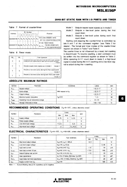
- Page 212 and 213: MITSUBISHI MICROCOMPUTERSMSL81S6P20
- Page 216 and 217: MITSUBISHI MICROCOMPUTERSM5L8156P20
- Page 218: MIC-ROCOMPUTER SUPPORT SYSTEMS
- Page 221 and 222: MITSUBISHI MICROCOMPUTERSPC4000DEBU
- Page 223 and 224: MITSUBISHI MICROCOMPUTERSPC4000DEBU
- Page 225 and 226: MITSUBISHI MICROCOMPUTERSPC9000CROS
- Page 227 and 228: MITSUBISHI MICROCOMPUTERSPC9100IS-B
- Page 229 and 230: MITSUBISHI MICROCOMPUTERSPC910018-8
- Page 231 and 232: MITSUBISHI MICROCOMPUTERSPC9001CPMC
- Page 233 and 234: MITSUBISHI MICROCOMPUTERSPC9004INTE
- Page 235 and 236: MI.TSUBISHI MICROCOMPUTERSPCA4040ME
- Page 237 and 238: MITSUBISHI MICROCOMPUTERSPCA4060MEL
- Page 240 and 241: MITSUBISHI MICROCOMPUTERSPCA4360MEL
- Page 242 and 243: MITSUBISHI MICROCOMPUTERSPCA8400.ME
- Page 244: APPENDICES
- Page 247 and 248: MITSUBISHI MICROCOMPUTERSMELPs 760
- Page 249 and 250: MITSUBISHI MICROCOMPUTERSMELPS 740
- Page 251 and 252: MITSUBISHI MICROCOMPUTERSMELPS 8-48
- Page 253 and 254: MITSUBISHI MICROCOMPUTERSMELPS 8-41
- Page 256 and 257: CONTACT ADDRESSES FOR FURTHER INFOR
- Page 258 and 259: 1984 MITSUBISHI DATA BOOKSINGLE-CHI
- Page 260 and 261: MITSUBISHI MICROCOMPUT~K:'MSL8048-X
- Page 262 and 263: MITSUBISHI MICROCOMPUTERSMSL8049H-X
- Page 264 and 265:
MITSUBISHI MICROCOMPUTERSMSM80S0L-X
- Page 266 and 267:
MEMO


