

COUPLINGS
COUPLINGS
COUPLINGS

You also want an ePaper? Increase the reach of your titles
YUMPU automatically turns print PDFs into web optimized ePapers that Google loves.
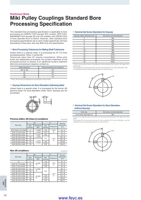
Technical DataMiki Pulley Couplings Standard BoreProcessing SpecificationThis standard bore processing specifi cation is applicable to boreprocessing for SERVO FLEX (except SFC model), SPR FLEX,BAUMANN FLEX (except ZG and LM models), and CENTA FLEXof bore diameter 6mm to 65mm. However, other standard boreprocessing specifi cations set to each model respectively will haveprecedence if they exist, and may differ from this specification. Bore Processing Tolerances for Mating Shaft TolerancesUnless there is a special order, it is processed by H7. For boreprocessing below 10mm, it will be H8.Tolerances other than H7 require consultation. When pilotbores are additionally processed, the surface treatment of theprocessed portion is shaved. If an additional surface treatmentafter bore processing is required, contact us.Shaft toleranceRecommended bore toleranceh6 to h9H7j6G7k6F7m6F7* The j6, k6 and m6 are adopted as new standard motor shafts. Nominal Set Screw Diameters for KeywayKeyway Basic dimension b2Set screw nominal diameter4 M45 M46 M57 M68 M610 M812 M814 M1015 M1016 M1018 M10* If this is not a special order, the positions of set screws will be 2 points, 90° apart fromeach other.* The positions for set screws may vary for some products. For more information, seethe standard bore processing specifi cation for each product.90°2-M Keyway Dimensions for Bore Diameters (following table)Unless there is a special order, it is processed by the former JIS(second class). For bore diameters under 12mm, keyways are notprocessed. Nominal Set Screw Diameters for Bore Diameters(without keyway)Previous edition JIS (Class 2) complianceBore dia.Basicdimensionb2Tolerance(E9)t2BasicTolerancedimension1.5 + 0.303.0Unit [mm]Keywaydimensionb×h12 or more, 13 or lessOver 13, 20 or less45+ 0.050+ 0.020 2.04× 45× 5Over 20, 30 or less 7 + 0.0617× 7Over 30, 40 or less 10 + 0.02510× 83.5 + 0.3Over 40, 50 or less 1212× 8+ 0.0750Over 50, 60 or less 15 5.0 15×10+ 0.032Over 60, 65 or less 18 6.0 18×12Bore dia.Set screw nominal diameter6 or more, less than 12 M4* If this is not a special order, the positions of set screws will be 2 points, 90° apart from eachother.* The positions for set screws may vary for some products. For more information, see thestandard bore processing specifi cation for each product.90°2-MNew JIS complianceUnit [mm]TechnicaldataBore dia.Basicdimension12 4b2Tolerance(H9)Basicdimensiont2ToleranceKeywaydimensionb×h1.84× 4+ 0.030+ 0.3Over 12, 17 or less 502.3 5× 50Over 17, 22 or less 6 2.8 6× 6Over 22, 30 or less 8 + 0.0368× 7Over 30, 38 or less 10 0 3.310× 8Over 38, 44 or less 12+ 0.3 12× 8Over 44, 50 or less 14 + 0.043 3.8 0 14× 9Over 50, 58 or less 16 0 4.3 16×10Over 58, 65 or less 18 4.4 18×1198www.feyc.es


