

COUPLINGS
COUPLINGS
COUPLINGS

Create successful ePaper yourself
Turn your PDF publications into a flip-book with our unique Google optimized e-Paper software.
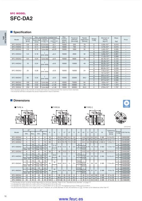
SFC MODELSFC-DA2SERVO FLEXSFC• SpecificationModelPermissibletorque[N·m]Max. permissible misalignmentParallel offset[mm]Angularmisalignment[ ˚ ]Axialdisplacement[mm]Max.rotationspeed[min –1 ]Torsionalstiffness[N·m/rad]Radialdisplacement[N/mm]ShapeTYPEMoment ofinertia[kg·m 2 ]SFC-005DA2 0.6 0.05 0.5 (one side) ±0.1 10000 250 70 C 0.36×10 –6 0.010 –SFC-010DA2 1.0 0.11 1 (one side) ±0.2 10000 700 70 C 0.79×10 –6 0.015 –SFC-020DA2 2.0 0.15 1 (one side) ±0.33 10000 1850 32 C 3.40×10 –6 0.035 –SFC-030DA2 5.0 0.181(one side)±0.4 10000 4000 32Mass[kg]PriceA 7.33×10 –6 0.053 –B 9.39×10 –6 0.061 –C 11.45×10 –6 0.069 –SFC-035DA2 8.0 0.24 1 (one side) ±0.5 10000 9000 56 C 26.78×10 –6 0.123 –SFC-040DA2 10 0.24SFC-050DA2 25 0.28SFC-060DA2 60 0.341(one side)1(one side)1(one side)±0.6 10000 10000 40±0.8 10000 16000 24±0.9 10000 35000 38.2A 29.49×10 –6 0.122 –B 36.05×10 –6 0.136 –C 42.61×10 –6 0.151 –A 96.94×10 –6 0.246 –B 119.2×10 –6 0.275 –C 141.4×10 –6 0.304 –A 252.4×10 –6 0.440 –B 314.8×10 –6 0.498 –C 377.3×10 –6 0.556 –SFC-080DA2 100 0.52 1 (one side) ±1.10 10000 70000 64 C 1034×10 –6 1.051 –SFC-090DA2 180 0.52 1 (one side) ±1.30 10000 50000 54 C 1776×10 –6 1.373 –SFC-100DA2 250 0.52 1 (one side) ±1.48 10000 60000 55.5 C 2704×10 –6 1.707 –* The indicated values in the moment of inertia and mass are measured with the maximum bore diameter.* The torsional stiffness indicates the actual measurement value of element.• DimensionsTYPE A TYPE B TYPE CLLSLPSLF LP LFCCM M MLSLP LF CKCADNA1d1d3DNd1d3d2Dd1A2d3d2Dd2Modeld1* 1 d2* 1 D N L LF LP S A1 A2 C d3 K MMin. Max. Min. Max.Tighteningtorque[N·m]ShapeTYPEUnit [mm]CAD file No.SFC-005DA2 4 6 4 6 16 – 23.2 7.85 5.5 1.0 – 4.8 2.5 6.5 6.5 2-M2 0.4 to 0.5 C C005D2B1SFC-010DA2 4 8 4 8 19 – 25.9 9.15 5.5 1.05 – 5.8* 2 3.15 8.5 8.5 2-M2.5* 3 1.0 to 1.1* 3 C C010D2B1SFC-020DA2 5 10 5 10 26 – 32.3 10.75 7.5 1.65 – 9.5 3.3 10.6 10.6 2-M2.5 1.0 to 1.1 C C020D2B15 10 5 108 –A C030D2B121.6SFC-030DA2 5 10 Over 10 14 34 37.8 12.4 8 2.5 8 12.5 3.75 15 14.5 2-M3 1.5 to 1.9 B C030D2B2Over 10 14 Over 10 14 – – 12.5 C C030D2B3SFC-035DA2 8 16 8 16 39 – 48 15.5 11 3 – 14.0 4.5 17 17 2-M4 3.4 to 4.1 C C035D2B18 15 8 1511 –A C040D2B129.6SFC-040DA2 8 15 Over 15 19 44 48 15.5 11 3 11 17.0 4.5 20 19.5 2-M4 3.4 to 4.1 B C040D2B2Over 15 19 Over 15 19 – – 17.0 C C040D2B310 19 10 1914.5 –A C050D2B138SFC-050DA2 10 19 Over 19 25 56 59.8 20.5 14 2.4 14.5 22.0 6 26 26 2-M5 7.0 to 8.5 B C050D2B2Over 19 25 Over 19 25 – – 22.0 C C050D2B312 24 12 2417.5 –A C060D2B146SFC-060DA2 12 24 Over 24 30 68 73.3 25.2 16.5 3.2 17.5 26.5 7.75 31 31 2-M6 14 to 15 B C060D2B2Over 24 30 Over 24 30 – – 26.5 C C060D2B3SFC-080DA2 20 35 20 35 82 – 98 30 22 8 – 28 9 40 38 2-M8 27 to 30 C C080D2B1SFC-090DA2 25 40 25 40 94 – 98.6 30 22 8.3 – 34 9 47 42 2-M8 27 to 30 C C090D2B1SFC-100DA2 35 45 35 45 104 – 101.6 30 22 9.8 – 39 9 50 48 2-M8 27 to 30 C C100D2B1* *1 Permissible torque could be limited depending on the bore diameter. Refer to the “Standard bore diameter” on page 17.* *2 indicates the value when d1 or d2 is ø4 to ø7. It will be 6.0 if d1 or d2 is ø8.* *3 indicates the value when d1 or d2 is ø4 to ø7. It will be M2 if d1 or d2 is ø8. The tightening torque of M2 is 0.4 to 0.5N·m.+ 0.010* The dimensional tolerance of the target shaft is h7. However, for a shaft diameter of ø35, the tolerance is - 0.025. Contact us for tolerances other than h7.16COUPLING_E_10_21new.indd 16www.feyc.es9/15/10 4:18 PM


