

COUPLINGS
COUPLINGS
COUPLINGS

You also want an ePaper? Increase the reach of your titles
YUMPU automatically turns print PDFs into web optimized ePapers that Google loves.
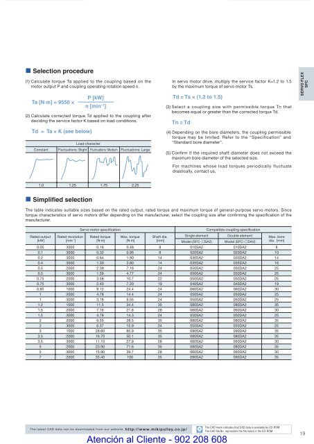
• Selection procedure(1) Calculate torque Ta applied to the coupling based on themotor output P and coupling operating rotation speed n.Ta [N·m] = 9550 ×Td = Ta × K (see below)P [kW]n [min −1 ](2) Calculate corrected torque Td applied to the coupling afterdeciding the service factor K based on load conditions.Load characterConstant Fluctuations: Slight Fluctuations: Medium Fluctuations: LargeIn servo motor drive, multiply the service factor K=1.2 to 1.5by the maximum torque of servo motor Ts.Td = Ts × (1.2 to 1.5)(3) Select a coupling size with permissible torque Tn thatbecomes equal or greater than the corrected torque Td.Tn ≥ Td(4) Depending on the bore diameters, the coupling permissibletorque may be limited. Refer to the “Specification” and“Standard bore diameter”.(5) Confirm if the required shaft diameter does not exceed themaximum bore diameter of the selected size.For machines whose load torques periodically fluctuatedrastically, contact us.SERVO FLEXSFC1.0 1.25 1.75 2.25• Simplified selectionThe table indicates suitable sizes based on the rated output, rated torque and maximum torque of general-purpose servo motors. Sincetorque characteristics of servo motors differ depending on the manufacturer, select the coupling size after confi rming the specifi cation of themanufacturer.Servo motor specifi cationCompatible coupling specifi cationRated output[kW]Rated revolution[min –1 ]Rated torque[N·m]Max. torque[N·m]Shaft dia.[mm]Single element Double element Max. boreModel (SFC-£SA2) Model (SFC-£DA2) dia. [mm]0.05 3000 0.16 0.48 8 010SA2 010DA2 80.1 3000 0.32 0.95 8 020SA2 020DA2 100.2 3000 0.64 1.90 14 030SA2 030DA2 140.4 3000 1.30 3.80 14 035SA2 035DA2 160.5 2000 2.39 7.16 24 050SA2 050DA2 250.5 3000 1.59 4.77 24 050SA2 050DA2 250.75 2000 3.58 10.7 22 050SA2 050DA2 250.75 3000 2.40 7.20 19 040SA2 040DA2 190.85 1000 8.12 24.4 24 060SA2 060DA2 301 2000 4.78 14.4 24 050SA2 050DA2 251 3000 3.18 9.55 24 050SA2 050DA2 251.2 1000 11.5 34.4 35 080SA2 080DA2 351.5 2000 7.16 21.6 28 060SA2 060DA2 301.5 3000 4.78 14.3 24 050SA2 050DA2 252 2000 9.55 28.5 35 080SA2 080DA2 352 3000 6.37 15.9 24 050SA2 050DA2 253 1000 28.60 85.9 35 090SA2 090DA2 353.5 2000 16.70 50.1 35 080SA2 080DA2 353.5 3000 11.10 27.9 28 060SA2 060DA2 305 2000 23.90 71.6 35 080SA2 080DA2 355 3000 15.90 39.7 28 060SA2 060DA2 307 2000 33.40 100 35 090SA2 090DA2 35The latest CAD data can be downloaded from our website. http://www.mikipulley.co.jp/COUPLING_E_10_21new.indd 19CADAtención al Cliente - 902 208 608The CAD mark indicates that CAD data is available by CD-ROM.The CAD fi le No. represents the fi le name in the CD-ROM.199/15/10 4:18 PM


