

COUPLINGS
COUPLINGS
COUPLINGS

You also want an ePaper? Increase the reach of your titles
YUMPU automatically turns print PDFs into web optimized ePapers that Google loves.
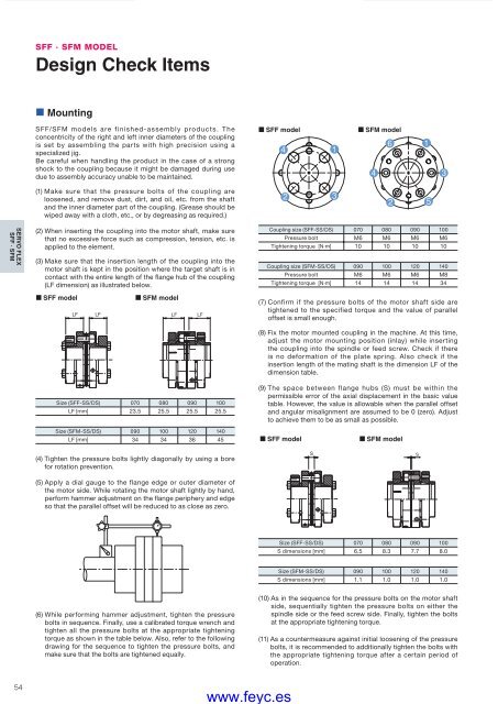
SFF · SFM MODELDesign Check Items• MountingSFF/SFM models are finished-assembly products. Theconcentricity of the right and left inner diameters of the couplingis set by assembling the parts with high precision using aspecialized jig.Be careful when handling the product in the case of a strongshock to the coupling because it might be damaged during usedue to assembly accuracy unable to be maintained.(1) Make sure that the pressure bolts of the coupling areloosened, and remove dust, dirt, and oil, etc. from the shaftand the inner diameter part of the coupling. (Grease should bewiped away with a cloth, etc., or by degreasing as required.)SFF modelSFM modelSERVO FLEXSFF · SFM(2) When inserting the coupling into the motor shaft, make surethat no excessive force such as compression, tension, etc. isapplied to the element.(3) Make sure that the insertion length of the coupling into themotor shaft is kept in the position where the target shaft is incontact with the entire length of the flange hub of the coupling(LF dimension) as illustrated below.SFF modelLFSFM modelLF LF LFCoupling size (SFF-SS/DS) 070 080 090 100Pressure bolt M6 M6 M6 M6Tightening torque [N·m] 10 10 10 10Coupling size (SFM-SS/DS) 090 100 120 140Pressure bolt M6 M6 M6 M8Tightening torque [N·m] 14 14 14 34(7) Confirm if the pressure bolts of the motor shaft side aretightened to the specified torque and the value of paralleloffset is small enough.Size (SFF-SS/DS) 070 080 090 100LF [mm] 23.5 25.5 25.5 25.5(8) Fix the motor mounted coupling in the machine. At this time,adjust the motor mounting position (inlay) while insertingthe coupling into the spindle or feed screw. Check if thereis no deformation of the plate spring. Also check if theinsertion length of the mating shaft is the dimension LF of thedimension table.(9) The space between flange hubs (S) must be within thepermissible error of the axial displacement in the basic valuetable. However, the value is allowable when the parallel offsetand angular misalignment are assumed to be 0 (zero). Adjustto achieve them to be as small as possible.Size (SFM-SS/DS) 090 100 120 140LF [mm] 34 34 36 45SFF modelSFM model(4) Tighten the pressure bolts lightly diagonally by using a borefor rotation prevention.SS(5) Apply a dial gauge to the flange edge or outer diameter ofthe motor side. While rotating the motor shaft lightly by hand,perform hammer adjustment on the flange periphery and edgeso that the parallel offset will be reduced to as close as zero.Size (SFF-SS/DS) 070 080 090 100S dimensions [mm] 6.5 8.3 7.7 8.0Size (SFM-SS/DS) 090 100 120 140S dimensions [mm] 1.1 1.0 1.0 1.0(6) While performing hammer adjustment, tighten the pressurebolts in sequence. Finally, use a calibrated torque wrench andtighten all the pressure bolts at the appropriate tighteningtorque as shown in the table below. Also, refer to the followingdrawing for the sequence to tighten the pressure bolts, andmake sure that the bolts are tightened equally.(10) As in the sequence for the pressure bolts on the motor shaftside, sequentially tighten the pressure bolts on either thespindle side or the feed screw side. Finally, tighten the boltsat the appropriate tightening torque.(11) As a countermeasure against initial loosening of the pressurebolts, it is recommended to additionally tighten the bolts withthe appropriate tightening torque after a certain period ofoperation.54COUPLING_E_42_55new.indd 54www.feyc.es9/15/10 4:26 PM


