

COUPLINGS
COUPLINGS
COUPLINGS

You also want an ePaper? Increase the reach of your titles
YUMPU automatically turns print PDFs into web optimized ePapers that Google loves.
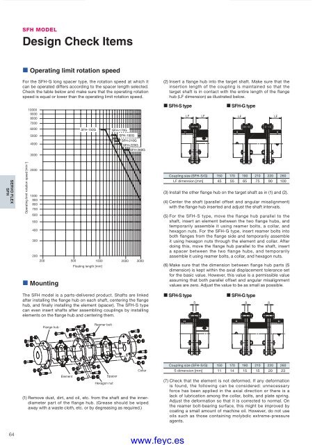
SFH MODELDesign Check Items• Operating limit rotation speedFor the SFH-G long spacer type, the rotation speed at which itcan be operated differs according to the spacer length selected.Check the table below and make sure that the operating rotationspeed is equal or lower than the operating limit rotation speed.(2) Insert a flange hub into the target shaft. Make sure that theinsertion length of the coupling is maintained so that thetarget shaft is in contact with the entire length of the flangehub (LF dimension) as illustrated below.10000900080007000• SFH-S type• SFH-G typeLF LFLF LF6000SFH-150GSFH-170G5000SFH-190G4000SFH-210GSFH-220GSFH-260G3000SERVO FLEXSFHOperating limit rotation speed [min –1 ]20001000900800700600500400300200200 500 1000 2000 3000• MountingFloating length [mm]Coupling size (SFH-S/G) 150 170 190 210 220 260LF dimension [mm] 45 55 65 75 90 100(3) Install the other flange hub on the target shaft as in (1) and (2).(4) Center the shaft (parallel offset and angular misalignment)with the flange hub inserted and adjust the shaft intervals.(5) For the SFH-S type, move the flange hub parallel to theshaft, insert an element between the two flange hubs, andtemporarily assemble it using reamer bolts, a collar, andhexagon nuts. For the SFH-G type, insert reamer bolts intoboth flanges from the flange side and temporarily assembleit using hexagon nuts through the element and collar. Afterdoing this, move the flange hub parallel to the shaft, inserta spacer between the two flange hubs, and temporarilyassemble it using reamer bolts, a collar, and hexagon nuts.(6) Make sure that the dimension between flange hub parts (Sdimension) is kept within the axial displacement tolerance setfor the basic value. However, this value is a permissible valueassuming that both parallel offset and angular misalignmentvalues are zero. Adjust the value to be as small as possible.The SFH model is a parts-delivered product. Shafts are linkedafter installing the flange hub on each shaft, centering the flangehub, and fi nally installing the element (spacer). The SFH-S typecan even insert shafts after assembling couplings by installingelements on the flange hub and centering them.• SFH-S typeS• SFH-G typeSSFlange hubReamer boltElementSpacerHexagon nutCollar(1) Remove dust, dirt, and oil, etc. from the shaft and the innerdiameterpart of the flange hub. (Grease should be wipedaway with a waste cloth, etc. or by degreasing as required.)Coupling size (SFH-S/G) 150 170 190 210 220 260S dimension [mm] 11 14 15 15 20 23(7) Check that the element is not deformed. If any deformationis found, the following can be considered: unnecessaryforce has been applied in the axial direction or there is alack of lubrication among the collar, bolts, and plate spring.Adjust the deformation so that it is corrected to normal. Onthe reamer bolt-bearing surface, this might be improved bycoating a small amount of machine oil. However, do not useoils such as those containing molybdic extreme-pressureagents.64COUPLING_E_56_65new.indd 64www.feyc.es9/15/10 4:29 PM


