

COUPLINGS
COUPLINGS
COUPLINGS

You also want an ePaper? Increase the reach of your titles
YUMPU automatically turns print PDFs into web optimized ePapers that Google loves.
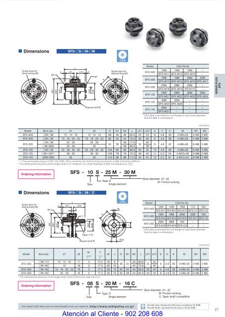
• DimensionsSFS-£S-£M-£MCADScrew bore fordismounting M2CM1DN1d1LF1SLLF2CM1d2N2Reamer bolt MKScrew bore fordismounting M2ModelCAD file No.SFS-06S12M 14M 15M −SFS-M11 SFS-M12 SFS-M13 −SFS-08S15M 16M 20M 22MSFS-M14 SFS-M15 SFS-M16 SFS-M17SFS-09S25M 28M 35M −SFS-M18 SFS-M19 SFS-M110 −SFS-10S25M 28M 30M 35MSFS-M21 SFS-M22 SFS-M23 SFS-M24SFS-12S30M 35M − −SFS-M25 SFS-M26 − −SFS-14S35M − − −SFS-M27 − − −* CAD data is provided for one fl ange for each bore diameter.Use the data in combination.SERVO FLEXSFSUnit [mm]Model Bore dia. d1 d2 D N1 N2 L LF1 LF2 S C K M M1 M2SFS-06S £M-£M 12 · 14 · 15 12 · 14 · 15 68 40 40 65.6 25 25 6 4.8 30 4-M6×25 4-M5 2-M5SFS-08S £M-£M 15 · 16 · 20 · 22 15 · 16 · 20 · 22 82 54 54 75.6 30 30 6 4.8 38 4-M6×29 4-M6 2-M6SFS-09S£M-£M 25 · 28 25 · 2858 77.6 3094 5830£M-35M 25 · 28 35 68 85.6 388 4.8 42 4-M8×36 6-M6 2-M6SFS-10S £M-£M 25 · 28 · 30 · 35 25 · 28 · 30 · 35 104 68 68 89.6 35 35 10 4.8 48 4-M8×36 6-M6 2-M6SFS-12S £M-£M*1 30 · 35 30 · 35 126 78 78 101.6 40 40 11 5.3 54 4-M10×45 4-M8 2-M8SFS-14S 35M-35M 35 35 144 88 88 112.6 45 45 12 5.3 61 4-M12×54 6-M8 2-M8* *1 The permissible torque of SFS-12S-30M-£M is limited by the shaft locking mechanism of ø30 and will be 380N·m.+ 0.010* The dimensional tolerance of the target shaft is h7. However, for a shaft diameter of ø35, the tolerance is - 0.025 .Ordering Information• DimensionsSFS - 10 S - 25 M - 30 MSizeSFS-£S-£M-£CType: SSingle elementBore diameter: d1- d2M: Friction lockingScrew bore fordismounting M2CM1DN1d1LF1LLF2SJd4N2Taper 1/10KCADWTModelCAD file No.SFS-06S12M 14M 15M 11C 16CSFS-M11 SFS-M12 SFS-M13 SFS-C1 SFS-C2SFS-08S15M 16M 20M 22M 16CSFS-M14 SFS-M15 SFS-M16 SFS-M17 SFS-C3SFS-09S25M 28M 16C − −SFS-M18 SFS-M19 SFS-C4 − −* CAD data is provided for one fl ange for each bore diameter.Use the data in combination.Reamer bolt Md2Unit [mm]Model Bore dia. d1 d2Ordering InformationW+0.0300SFS - 08 S - 20 M - 16 CSizeT+0.30d4 J D N1 N2 L LF1 LF2 S C K M M1 M2SFS-06S£M-11C 12 · 14 · 15 11 4 12.2 18 930 60.8 2568 4025£M-16C 15 16 5 17.3 28 10 40 75.8 406 4.8 30 4-M6×25 4-M5 2-M5SFS-08S £M-16C 15 · 16 · 20 · 22 16 5 17.3 28 10 82 54 40 80.8 30 40 6 4.8 38 4-M6×29 4-M6 2-M6SFS-09S £M-16C 25 · 28 16 5 17.3 28 10 94 58 40 82.8 30 40 8 4.8 42 4-M8×36 6-M6 2-M6* The dimensional tolerance of the target shaft of the friction lock-side hub is h7.Type: SSingle elementBore diameter: d1- d2M: Friction lockingC: Taper shaft compatibleThe latest CAD data can be downloaded from our website. http://www.mikipulley.co.jp/COUPLING_E_22_41new.indd 27CADAtención al Cliente - 902 208 608The CAD mark indicates that CAD data is available by CD-ROM.The CAD fi le No. represents the fi le name in the CD-ROM.279/15/10 4:23 PM


