

COUPLINGS
COUPLINGS
COUPLINGS

You also want an ePaper? Increase the reach of your titles
YUMPU automatically turns print PDFs into web optimized ePapers that Google loves.
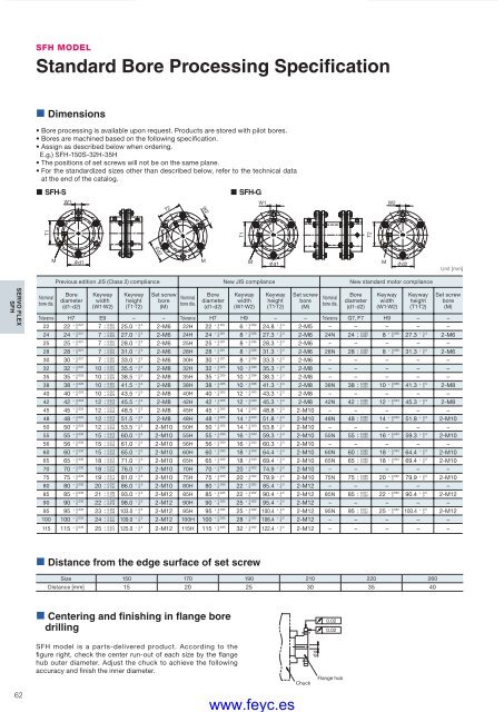
d2SFH MODELStandard Bore Processing Specification• Dimensions• Bore processing is available upon request. Products are stored with pilot bores.• Bores are machined based on the following specification.• Assign as described below when ordering.E.g.) SFH-150S-32H-35H• The positions of set screws will not be on the same plane.• For the standardized sizes other than described below, refer to the technical dataat the end of the catalog.• SFH-S• SFH-GW1T2W2W1W2T1T1T2Md1MMd1Md2Unit [mm]Previous edition JIS (Class 2) compliance New JIS compliance New standard motor complianceSERVO FLEXSFHNominalbore dia.Borediameter(d1-d2)Keywaywidth(W1·W2)Keywayheight(T1·T2)Set screwbore(M)Nominalbore dia.Borediameter(d1-d2)Keywaywidth(W1·W2)Keywayheight(T1·T2)Set screwbore(M)Nominalbore dia.Borediameter(d1-d2)Keywaywidth(W1·W2)Tolerance H7 E9 – – Tolerance H7 H9 – – Tolerance G7, F7 H9 – –22 22 + 0.0210 7 + 0.061+ 0.025 25.0 + 0.30 2-M6 22H 22 + 0.0210 6 + 0.0300 24.8 + 0.30 2-M5 – – – – –24 24 + 0.0210 7 + 0.061+ 0.025 27.0 + 0.30 2-M6 24H 24 + 0.0210 8 + 0.0360 27.3 + 0.30 2-M6 24N 24 + 0.028+ 0.007 8 + 0.0360 27.3 + 0.30 2-M625 25 + 0.0210 7 + 0.061+ 0.025 28.0 + 0.30 2-M6 25H 25 + 0.0210 8 + 0.0360 28.3 + 0.30 2-M6 – – – – –28 28 + 0.0210 7 + 0.061+ 0.025 31.0 + 0.30 2-M6 28H 28 + 0.0210 8 + 0.0360 31.3 + 0.30 2-M6 28N 28 + 0.028+ 0.007 8 + 0.0360 31.3 + 0.30 2-M630 30 + 0.0210 7 + 0.061+ 0.025 33.0 + 0.30 2-M6 30H 30 + 0.0210 8 + 0.0360 33.3 + 0.30 2-M6 – – – – –32 32 + 0.0250 10 + 0.061+ 0.025 35.5 + 0.30 2-M8 32H 32 + 0.0250 10 + 0.0360 35.3 + 0.30 2-M8 – – – – –35 35 + 0.0250 10 + 0.061+ 0.025 38.5 + 0.30 2-M8 35H 35 + 0.0250 10 + 0.0360 38.3 + 0.30 2-M8 – – – – –38 38 + 0.0250 10 + 0.061+ 0.025 41.5 + 0.30 2-M8 38H 38 + 0.0250 10 + 0.0360 41.3 + 0.30 2-M8 38N 38 + 0.050+ 0.025 10 + 0.0360 41.3 + 0.30 2-M840 40 + 0.0250 10 + 0.061+ 0.025 43.5 + 0.30 2-M8 40H 40 + 0.0250 12 + 0.0430 43.3 + 0.30 2-M8 – – – – –42 42 + 0.0250 12 + 0.075+ 0.032 45.5 + 0.30 2-M8 42H 42 + 0.0250 12 + 0.0430 45.3 + 0.30 2-M8 42N 42 + 0.050+ 0.025 12 + 0.0430 45.3 + 0.30 2-M845 45 + 0.0250 12 + 0.075+ 0.032 48.5 + 0.30 2-M8 45H 45 + 0.0250 14 + 0.0430 48.8 + 0.30 2-M10 – – – – –Keywayheight(T1·T2)Set screwbore(M)48 48 + 0.0250 12 + 0.075+ 0.032 51.5 + 0.30 2-M8 48H 48 + 0.0250 14 + 0.0430 51.8 + 0.30 2-M10 48N 48 + 0.050+ 0.025 14 + 0.0430 51.8 + 0.30 2-M1050 50 + 0.0250 12 + 0.075+ 0.032 53.5 + 0.30 2-M10 50H 50 + 0.0250 14 + 0.0430 53.8 + 0.30 2-M10 – – – – –55 55 + 0.0300 15 + 0.075+ 0.032 60.0 + 0.30 2-M10 55H 55 + 0.0300 16 + 0.0430 59.3 + 0.30 2-M10 55N 55 + 0.060+ 0.030 16 + 0.0430 59.3 + 0.30 2-M1056 56 + 0.0300 15 + 0.075+ 0.032 61.0 + 0.30 2-M10 56H 56 + 0.0300 16 + 0.0430 60.3 + 0.30 2-M10 – – – – –60 60 + 0.0300 15 + 0.075+ 0.032 65.0 + 0.30 2-M10 60H 60 + 0.0300 18 + 0.0430 64.4 + 0.30 2-M10 60N 60 + 0.060+ 0.030 18 + 0.0430 64.4 + 0.30 2-M1065 65 + 0.0300 18 + 0.075+ 0.032 71.0 + 0.30 2-M10 65H 65 + 0.0300 18 + 0.0430 69.4 + 0.30 2-M10 65N 65 + 0.060+ 0.030 18 + 0.0430 69.4 + 0.30 2-M1070 70 + 0.0300 18 + 0.075+ 0.032 76.0 + 0.30 2-M10 70H 70 + 0.0300 20 + 0.0520 74.9 + 0.50 2-M10 – – – – –75 75 + 0.0300 19 + 0.011+ 0.054 81.0 + 0.50 2-M10 75H 75 + 0.0300 20 + 0.0520 79.9 + 0.50 2-M10 75N 75 + 0.060+ 0.030 20 + 0.0520 79.9 + 0.50 2-M1080 80 + 0.0300 20 + 0.097+ 0.140 86.0 + 0.50 2-M10 80H 80 + 0.0300 22 + 0.0520 85.4 + 0.50 2-M12 – – – – –85 85 + 0.0350 21 + 0.183+ 0.226 93.0 + 0.50 2-M12 85H 85 + 0.0350 22 + 0.0520 90.4 + 0.50 2-M12 85N 85 + 0.071+ 0.036 22 + 0.0520 90.4 + 0.50 2-M1290 90 + 0.0350 22 + 0.269+ 0.312 98.0 + 0.50 2-M12 90H 90 + 0.0350 25 + 0.0520 95.4 + 0.50 2-M12 – – – – –95 95 + 0.0350 23 + 0.355+ 0.398 103.0 + 0.50 2-M12 95H 95 + 0.0350 25 + 0.0520 100.4 + 0.50 2-M12 95N 95 + 0.071+ 0.036 25 + 0.0520 100.4 + 0.50 2-M12100 100 + 0.0350 24 + 0.441+ 0.484 109.0 + 0.50 2-M12 100H 100 + 0.0350 28 + 0.0520 106.4 + 0.50 2-M12 – – – – –115 115 + 0.0350 25 + 0.527+ 0.570 125.0 + 0.50 2-M12 115H 115 + 0.0350 32 + 0.0520 122.4 + 0.50 2-M12 – – – – –• Distance from the edge surface of set screwSize 150 170 190 210 220 260Distance [mm] 15 20 25 30 35 40• Centering and finishing in flange boredrilling0.020.0262SFH model is a parts-delivered product. According to thefi gure right, check the center run-out of each size by the fl angehub outer diameter. Adjust the chuck to achieve the followingaccuracy and finish the inner diameter.COUPLING_E_56_65new.indd 62www.feyc.esChuckdFlange hub9/15/10 4:29 PM


