

COUPLINGS
COUPLINGS
COUPLINGS

You also want an ePaper? Increase the reach of your titles
YUMPU automatically turns print PDFs into web optimized ePapers that Google loves.
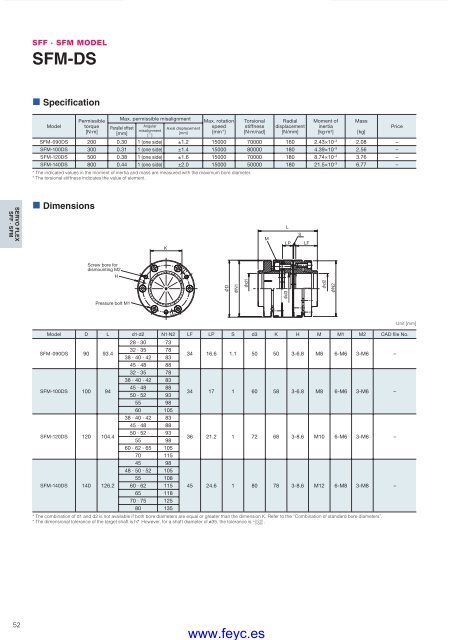
SFF · SFM MODELSFM-DS• SpecificationModelPermissibletorque[N·m]Max. permissible misalignmentParallel offset[mm]Angularmisalignment[ ˚ ]Axial displacement[mm]Max. rotationspeed[min -1 ]Torsionalstiffness[N·m/rad]Radialdisplacement[N/mm]Moment ofinertia[kg·m 2 ]SFM-090DS 200 0.30 1 (one side) ±1.2 15000 70000 160 2.43×10 –3 2.08 –SFM-100DS 300 0.31 1 (one side) ±1.4 15000 80000 180 4.39×10 –3 2.56 –SFM-120DS 500 0.38 1 (one side) ±1.6 15000 70000 180 8.74×10 –3 3.76 –SFM-140DS 800 0.44 1 (one side) ±2.0 15000 50000 180 21.5×10 –3 6.77 –* The indicated values in the moment of inertia and mass are measured with the maximum bore diameter.* The torsional stiffness indicates the value of element.Mass[kg]PriceSERVO FLEXSFF · SFM• DimensionsKMLLPSLFScrew bore fordismounting M2Hd3DN1d1d2N2Pressure bolt M1Model D L d1·d2 N1·N2 LF LP S d3 K H M M1 M2 CAD file No.SFM-090DS 90 93.4SFM-100DS 100 94SFM-120DS 120 104.4SFM-140DS 140 126.228 · 30 7332 · 35 7838 · 40 · 42 8345 · 48 8832 · 35 7838 · 40 · 42 8345 · 48 8850 · 52 9355 9860 10538 · 40 · 42 8345 · 48 8850 · 52 9355 9860 · 62 · 65 10570 11545 9848 · 50 · 52 10555 10860 · 62 11565 11870 · 75 12580 13534 16.6 1.1 50 50 3-6.8 M8 6-M6 3-M6 –34 17 1 60 58 3-6.8 M8 6-M6 3-M6 –36 21.2 1 72 68 3-8.6 M10 6-M6 3-M6 –45 24.6 1 80 78 3-8.6 M12 6-M8 3-M8 –* The combination of d1 and d2 is not available if both bore diameters are equal or greater than the dimension K. Refer to the “Combination of standard bore diameters”.* The dimensional tolerance of the target shaft is h7. However, for a shaft diameter of ø35, the tolerance is + 0.010- 0.025 .Unit [mm]52COUPLING_E_42_55new.indd 52www.feyc.es9/15/10 4:26 PM


