

COUPLINGS
COUPLINGS
COUPLINGS

Create successful ePaper yourself
Turn your PDF publications into a flip-book with our unique Google optimized e-Paper software.
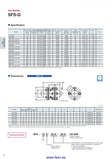
SFS MODELSFS-G• SpecificationSERVO FLEXSFSModelPermissibletorque[N·m]Max. permissible misalignmentParallel offset[mm]Angularmisalignment[ ˚ ]Axialdisplacement[mm]Max. rotationspeed[min -1 ]Torsionalstiffness[N·m/rad]Radialdisplacement[N/mm]Moment ofinertia[kg·m 2 ]SFS-05G 20 0.5 1 (one side) ±1.2 20000 8000 21 0.20×10 –3 0.50 –SFS-06G 40 0.5 1 (one side) ±1.6 16000 14000 22 0.55×10 –3 0.90 –SFS-06G-£M-£M 40 0.5 1 (one side) ±1.6 5000 14000 22 0.55×10 –3 1.10 –SFS-06G-£M-11C 40 0.5 1 (one side) ±1.6 5000 14000 22 0.54×10 –3 1.00 –SFS-06G-£M-16C 40 0.5 1 (one side) ±1.6 5000 14000 22 0.59×10 –3 1.10 –SFS-08G 80 0.5 1 (one side) ±2.0 13000 41000 30 1.50×10 –3 1.70 –SFS-08G-£M-£M 80 0.5 1 (one side) ±2.0 5000 41000 30 1.56×10 –3 2.00 –SFS-08G-£M-16C 80 0.5 1 (one side) ±2.0 5000 41000 30 1.47×10 –3 1.90 –SFS-09G 180 0.6 1 (one side) ±2.4 12000 85000 61 2.90×10 –3 2.40 –SFS-09G-£M-£M 180 0.6 1 (one side) ±2.4 5000 85000 61 3.10×10 –3 2.80 –SFS-09G-£M-16C 180 0.6 1 (one side) ±2.4 5000 85000 61 2.80×10 –3 2.60 –SFS-10G 250 0.6 1 (one side) ±2.8 10000 125000 80 4.60×10 –3 3.30 –SFS-10G-£M-£M 250 0.6 1 (one side) ±2.8 5000 125000 80 4.70×10 –3 3.50 –SFS-12G 450 0.8 1 (one side) ±3.2 8000 215000 98 11.80×10 –3 5.80 –SFS-12G-£M-£M 450 0.8 1 (one side) ±3.2 5000 215000 98 12.10×10 –3 6.50 –SFS-14G 800 0.9 1 (one side) ±3.6 7000 390000 156 21.20×10 –3 8.60 –SFS-14G-35M-35M 580 0.9 1 (one side) ±3.6 5000 390000 156 25.31×10 –3 10.10 –* The indicated values in the moment of inertia and mass are measured with the maximum bore diameter.Mass[kg]Price• DimensionsSFS-£GLLS S LFFCADKDNd1d2Reamer bolt MModeld1·d2Pilot bore Min. Max.D N L LF LS S F K M CAD file No.SFS-05G 7 8 20 56 32 74 20 24 5 11 24 8-M5×22 SFS-G1SFS-06G 7 8 25 68 40 86 25 24 6 10 30 8-M6×25 SFS-G2SFS-08G 12 14 35 82 54 98 30 26 6 11 38 8-M6×29 SFS-G3SFS-09G 12 14 38 94 58 106 30 30 8 21 42 8-M8×36 SFS-G4SFS-10G 20 22 42 104 68 120 35 30 10 16 48 8-M8×36 SFS-G5SFS-12G 20 22 50 126 78 140 40 38 11 23 54 8-M10×45 SFS-G6SFS-14G 20 22 60 144 88 160 45 46 12 31 61 8-M12×54 SFS-G7* Specify the required LS dimensions when requesting products other than the above LS dimensions. Contact us if the LS is equal or greater than 1000.* Pilot bores are drilled bores. For additional processing, refer to the "Standard bore processing specifi cation" on page 32.Unit [mm]Ordering InformationSFS - 10 G - 25 H - 30 HSizeType: GDouble elementFloating shaftLS=500Length of spacer* Blank if standard spacerBore diameter: d1- d2 with standard bore processingBlank: Previous edition JIS (Class 2) complianceH: New JIS complianceN: New standard motor compliance* Blank if bore processing is not required30COUPLING_E_22_41new.indd 30www.feyc.es9/15/10 4:23 PM


