

COUPLINGS
COUPLINGS
COUPLINGS

You also want an ePaper? Increase the reach of your titles
YUMPU automatically turns print PDFs into web optimized ePapers that Google loves.
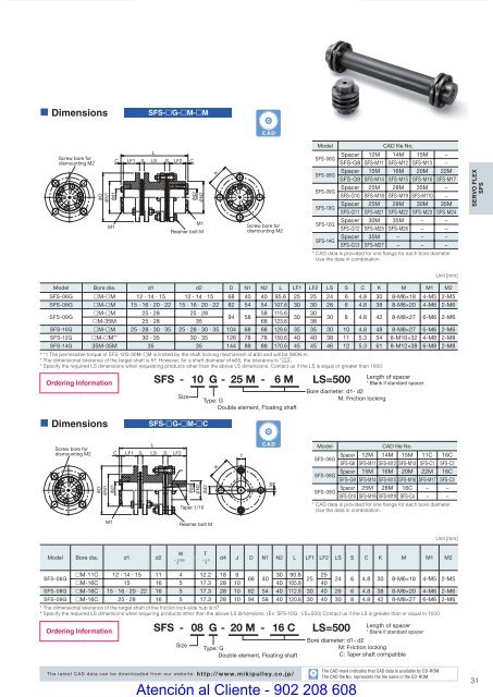
• DimensionsSFS-£G-£M-£MCADScrew bore fordismounting M2DN1LC LF1 S LS S LF2d1M1Cd2N2M1Reamer bolt MKScrew bore fordismounting M2ModelCAD file No.SFS-06GSpacer 12M 14M 15M −SFS-G8 SFS-M11 SFS-M12 SFS-M13 −SFS-08GSpacer 15M 16M 20M 22MSFS-G9 SFS-M14 SFS-M15 SFS-M16 SFS-M17SFS-09GSpacer 25M 28M 35M −SFS-G10 SFS-M18 SFS-M19 SFS-M110 −SFS-10GSpacer 25M 28M 30M 35MSFS-G11 SFS-M21 SFS-M22 SFS-M23 SFS-M24SFS-12GSpacer 30M 35M − −SFS-G12 SFS-M25 SFS-M26 − −SFS-14GSpacer 35M − − −SFS-G13 SFS-M27 − − −* CAD data is provided for one fl ange for each bore diameter.Use the data in combination.SERVO FLEXSFSUnit [mm]Model Bore dia. d1 d2 D N1 N2 L LF1 LF2 LS S C K M M1 M2SFS-06G £M-£M 12 · 14 · 15 12 · 14 · 15 68 40 40 95.6 25 25 24 6 4.8 30 8-M6×18 4-M5 2-M5SFS-08G £M-£M 15 · 16 · 20 · 22 15 · 16 · 20 · 22 82 54 54 107.6 30 30 26 6 4.8 38 8-M6×20 4-M6 2-M6SFS-09G£M-£M 25 · 28 25 · 2858 115.6 3094 5830£M-35M 25 · 28 35 68 123.6 3830 8 4.8 42 8-M8×27 6-M6 2-M6SFS-10G £M-£M 25 · 28 · 30 · 35 25 · 28 · 30 · 35 104 68 68 129.6 35 35 30 10 4.8 48 8-M8×27 6-M6 2-M6SFS-12G £M-£M* 1 30 · 35 30 · 35 126 78 78 150.6 40 40 38 11 5.3 54 8-M10×32 4-M8 2-M8SFS-14G 35M-35M 35 35 144 88 88 170.6 45 45 46 12 5.3 61 8-M12×38 6-M8 2-M8* *1 The permissible torque of SFS-12G-30M-£M is limited by the shaft locking mechanism of ø30 and will be 380N·m.+ 0.010* The dimensional tolerance of the target shaft is h7. However, for a shaft diameter of ø35, the tolerance is - 0.025.* Specify the required LS dimensions when requesting products other than the above LS dimensions. Contact us if the LS is equal or greater than 1000.Ordering InformationSFS - 10 G - 25 M - 6 MSizeType: GDouble element, Floating shaftLS=500Length of spacer* Blank if standard spacerBore diameter: d1- d2M: Friction locking• DimensionsSFS-£G-£M-£CScrew bore fordismounting M2DN1d1LC LF1 S LS SLF2d4N2d2Taper 1/10KTCADWModelCAD file No.SFS-06GSpacer 12M 14M 15M 11C 16CSFS-G8 SFS-M11 SFS-M12 SFS-M13 SFS-C1 SFS-C2SFS-08GSpacer 15M 16M 20M 22M 16CSFS-G9 SFS-M14 SFS-M15 SFS-M16 SFS-M17 SFS-C3SFS-09GSpacer 25M 28M 16C − −SFS-G10 SFS-M18 SFS-M19 SFS-C4 − −* CAD data is provided for one fl ange for each bore diameter.Use the data in combination.M1Reamer bolt MUnit [mm]Model Bore dia. d1 d2W+ 0.0300T+ 0.30d4 J D N1 N2 L LF1 LF2 LS S C K M M1 M2SFS-06G£M-11C 12 · 14 · 15 11 4 12.2 18 930 90.8 2568 4025£M-16C 15 16 5 17.3 28 10 40 105.8 4024 6 4.8 30 8-M6×18 4-M5 2-M5SFS-08G £M-16C 15 · 16 · 20 · 22 16 5 17.3 28 10 82 54 40 112.8 30 40 26 6 4.8 38 8-M6×20 4-M6 2-M6SFS-09G £M-16C 25 · 28 16 5 17.3 28 10 94 58 40 120.8 30 40 30 8 4.8 42 8-M8×27 6-M6 2-M6* The dimensional tolerance of the target shaft of the friction lock-side hub is h7.* Specify the required LS dimensions when requiring products other than the above LS dimensions. (Ex: SFS-10G LS=500) Contact us if the LS is greater than or equal to 1000.Ordering InformationSFS - 08 G - 20 M - 16 CSizeType: GDouble element, Floating shaftLS=500Length of spacer* Blank if standard spacerBore diameter: d1- d2M: Friction lockingC: Taper shaft compatibleThe latest CAD data can be downloaded from our website. http://www.mikipulley.co.jp/COUPLING_E_22_41new.indd 31CADAtención al Cliente - 902 208 608The CAD mark indicates that CAD data is available by CD-ROM.The CAD fi le No. represents the fi le name in the CD-ROM.319/15/10 4:23 PM


