

COUPLINGS
COUPLINGS
COUPLINGS

You also want an ePaper? Increase the reach of your titles
YUMPU automatically turns print PDFs into web optimized ePapers that Google loves.
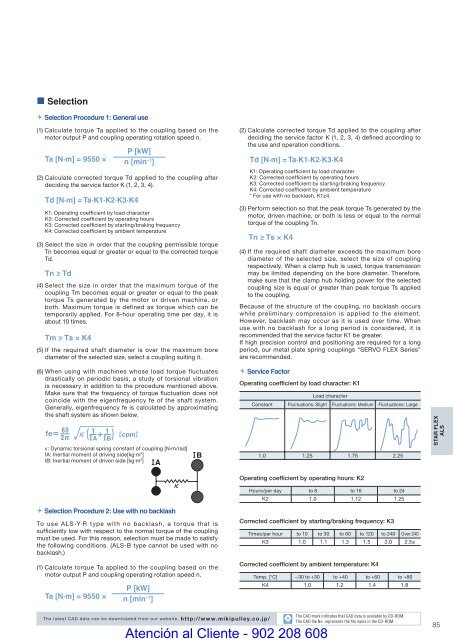
• Selection Selection Procedure 1: General use(1) Calculate torque Ta applied to the coupling based on themotor output P and coupling operating rotation speed n.Ta [N·m] = 9550 ×Td [N·m] = Ta·K1·K2·K3·K4P [kW]n [min −1 ](2) Calculate corrected torque Td applied to the coupling afterdeciding the service factor K (1, 2, 3, 4).K1: Operating coeffi cient by load characterK2: Corrected coeffi cient by operating hoursK3: Corrected coeffi cient by starting/braking frequencyK4: Corrected coefficient by ambient temperature(3) Select the size in order that the coupling permissible torqueTn becomes equal or greater or equal to the corrected torqueTd.Tn ≥ Td(4) Select the size in order that the maximum torque of thecoupling Tm becomes equal or greater or equal to the peaktorque Ts generated by the motor or driven machine, orboth. Maximum torque is defined as torque which can betemporarily applied. For 8-hour operating time per day, it isabout 10 times.Tm ≥ Ts × K4(5) If the required shaft diameter is over the maximum borediameter of the selected size, select a coupling suiting it.(2) Calculate corrected torque Td applied to the coupling afterdeciding the service factor K (1, 2, 3, 4) defined according tothe use and operation conditions.Td [N·m] = Ta·K1·K2·K3·K4K1: Operating coeffi cient by load characterK2: Corrected coeffi cient by operating hoursK3: Corrected coeffi cient by starting/braking frequencyK4: Corrected coefficient by ambient temperature* For use with no backlash, K1≥4.(3) Perform selection so that the peak torque Ts generated by themotor, driven machine, or both is less or equal to the normaltorque of the coupling Tn.Tn ≥ Ts × K4(4) If the required shaft diameter exceeds the maximum borediameter of the selected size, select the size of couplingrespectively. When a clamp hub is used, torque transmissionmay be limited depending on the bore diameter. Therefore,make sure that the clamp hub holding power for the selectedcoupling size is equal or greater than peak torque Ts appliedto the coupling.Because of the structure of the coupling, no backlash occurswhile preliminary compression is applied to the element.However, backlash may occur as it is used over time. Whenuse with no backlash for a long period is considered, it isrecommended that the service factor K1 be greater.If high precision control and positioning are required for a longperiod, our metal plate spring couplings “SERVO FLEX Series”are recommended.(6) When using with machines whose load torque fluctuatesdrastically on periodic basis, a study of torsional vibrationis necessary in addition to the procedure mentioned above.Make sure that the frequency of torque fl uctuation does notcoincide with the eigenfrequency fe of the shaft system.Generally, eigenfrequency fe is calculated by approximatingthe shaft system as shown below.K: Dynamic torsional spring constant of coupling [N·m/rad]IA: Inertial moment of driving side[kg·m 2 ]IB: Inertial moment of driven side [kg·m 2 ] Service FactorOperating coefficient by load character: K1Load characterConstant Fluctuations: Slight Fluctuations: Medium Fluctuations: Large1.0 1.25 1.75 2.25STAR FLEXALS Selection Procedure 2: Use with no backlashTo use ALS-Y·R type with no backlash, a torque that issufficiently low with respect to the normal torque of the couplingmust be used. For this reason, selection must be made to satisfythe following conditions. (ALS-B type cannot be used with nobacklash.)(1) Calculate torque Ta applied to the coupling based on themotor output P and coupling operating rotation speed n.P [kW]Ta [N·m] = 9550 × n [min −1 ]Operating coefficient by operating hours: K2Hours/per day to 8 to 16 to 24K2 1.0 1.12 1.25Corrected coefficient by starting/braking frequency: K3Times/per hour to 10 to 30 to 60 to 120 to 240 Over 240K3 1.0 1.1 1.3 1.5 2.0 2.5≤Corrected coefficient by ambient temperature: K4Temp. [°C] −30 to +30 to +40 to +60 to +80K4 1.0 1.2 1.4 1.8The latest CAD data can be downloaded from our website. http://www.mikipulley.co.jp/CADAtención al Cliente - 902 208 608The CAD mark indicates that CAD data is available by CD-ROM.The CAD fi le No. represents the fi le name in the CD-ROM.85


