

COUPLINGS
COUPLINGS
COUPLINGS

Create successful ePaper yourself
Turn your PDF publications into a flip-book with our unique Google optimized e-Paper software.
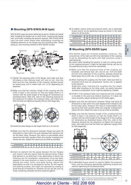
• Mounting (SFS-S/W/G-M-M type)SFS-S/W/G types are parts-delivered products. Shafts are linkedafter installing the flange hub on each shaft, centering the fl angehub, and finally installing the element (spacer). SFS-S/W/G-M-Mtype can even insert shafts after assembling couplings byinstalling elements on the flange hub and centering them. Whendoing so, see mounting method of SFS-SS/DS models.LFSReamer boltPressure boltLFCollarElementFlangeSleeveHexagon nut(1) Tighten the pressure bolts of the fl ange, and make sure thatthe sleeve is free. Remove dust, dirt, and oil, etc. from theshaft and the inner diameter of the coupling. (Grease shouldbe wiped away with a waste cloth, etc. or by degreasing asrequired.)(2) Make sure that the insertion length of the coupling into theshaft is kept in the position so that the target shaft is incontact with the entire length of the flange (LF dimension) asillustrated below. After this, refer to the following drawing forthe sequence to tighten the pressure bolts, and make surethat the bolts are tightened equally little by little diagonally.(6) To tighten reamer bolts and pressure bolts, use a calibratedtorque wrench at the tightening torque as shown in the tablebelow for all the bolts.Coupling size 05 06 08 09 10 12 14Reamer bolt M5 M6 M6 M8 M8 M10 M12Tightening torque [N·m] 8 14 14 34 34 68 118Pressure bolt M5 M6 M6 M6 M6 M8 M8Tightening torque [N·m] 8 14 14 14 14 34 34• Mounting (SFS-SS/DS type)SFS-SS/DS types are finished-assembly products. Theconcentricity of the right and left inner diameters of the couplingis set by assembling the parts with high precision using aspecialized jig.Be careful when handling the product in case of a strong shockto the coupling because it might be damaged during use due tothe assembly accuracy cannot be maintained.(1) Make sure that the pressure bolts of the coupling areloosened, and remove dust, dirt, and oil, etc. from the shaftand the inner diameter of the coupling. (Grease should bewiped away with a cloth, etc. or by degreasing as required.)(2) When inserting the coupling into the shaft, make sure that noexcessive force such as compression, tension, etc. is appliedto the element.Especially when inserting the coupling into the targetshaft after installing on the other shaft, be careful becauseexcessive compression force might be applied by mistake.(3) Confi rm if the pressure bolts are loosened and the couplingis movable to the axial and rotative directions. If it does notmove smoothly, adjust centering of both shafts again.(4) Make sure that the dimension between flange hub parts (Sdimension) is kept within the axial displacement tolerance setfor the basic value. However, this value is a permissible valueassuming that both parallel offset and angular misalignmentvalues are zero. Adjust the value to be as small as possible.SERVO FLEXSFS(3) Install the other flange on the target shaft as in (1) and (2).(4) Make sure that the dimension between flange hub parts (Sdimension) is kept within the axial displacement tolerance setfor the basic value. However, this value is a permissible valueassuming that both parallel offset and angular misalignmentvalues are zero. Adjust the value to be as small as possible.(5) Make sure that the insertion length of the coupling into theshaft is kept in the position so that the target shaft is incontact with the entire length of the flange hub of the coupling(LF dimension) as illustrated below. After this, refer to thefollowing drawing for the sequence to tighten the pressurebolts, and make sure that the bolts are tightened equally littleby little diagonally.LF LFSPressure boltCoupling size 05 06 08 09 10 12 14S dimension [mm] 5 6 6 8 10 11 12(5) Insert an element into the space between the two flangesand mount it with the reamer bolts for element fi xing. Checkthat element is not deformed. If any deformation is found, thefollowing can be considered: unnecessary force has beenapplied in the axial direction or there is a lack of lubricationamong the collar, bolts, and plate spring. Adjust thedeformation so that it is corrected to normal. On the reamerbolt-bearing surface, this might be improved by coating asmall amount of machine oil. However, do not use oils such asthose containing molybdic extreme-pressure agents.Coupling size 080 090 100 120 140S dimension [mm] 8 8 10 11 12LF dimension [mm] 26.5 26.5 30.5 30.5 36.5(6) A calibrated torque wrench is used to tighten the pressurebolts, and the following appropriate tightening torques areused for tightening all the pressure bolts.Coupling size 080 090 100 120 140Pressure bolt M6 M6 M6 M6 M8Tightening torque [N·m] 14 14 14 14 34The latest CAD data can be downloaded from our website. http://www.mikipulley.co.jp/COUPLING_E_22_41new.indd 39CADAtención al Cliente - 902 208 608The CAD mark indicates that CAD data is available by CD-ROM.The CAD fi le No. represents the fi le name in the CD-ROM.399/15/10 4:23 PM


