

COUPLINGS
COUPLINGS
COUPLINGS

You also want an ePaper? Increase the reach of your titles
YUMPU automatically turns print PDFs into web optimized ePapers that Google loves.
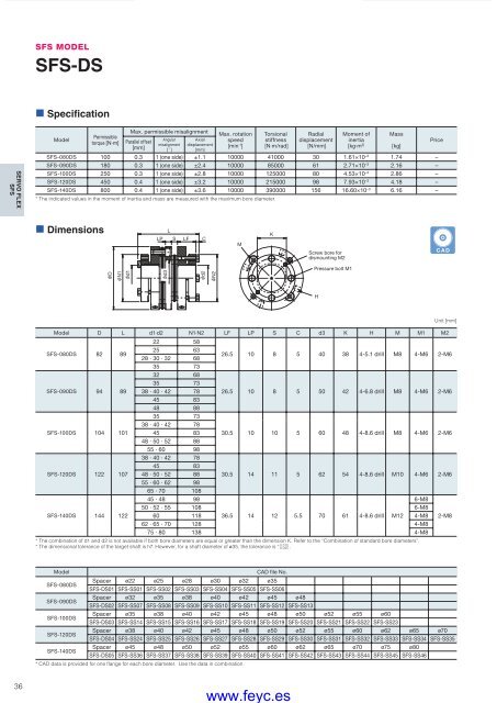
SFS MODELSFS-DS• SpecificationSERVO FLEXSFSModelPermissibletorque [N·m]Max. permissible misalignmentParallel offset[mm]Angularmisalignment[ ˚ ]Axialdisplacement[mm]Max. rotationspeed[min -1 ]* The indicated values in the moment of inertia and mass are measured with the maximum bore diameter.Torsionalstiffness[N·m/rad]Radialdisplacement[N/mm]Moment ofinertia[kg·m 2]SFS-080DS 100 0.3 1 (one side) ±1.1 10000 41000 30 1.61×10 –3 1.74 –SFS-090DS 180 0.3 1 (one side) ±2.4 10000 85000 61 2.71×10 –3 2.16 –SFS-100DS 250 0.3 1 (one side) ±2.8 10000 125000 80 4.53×10 –3 2.86 –SFS-120DS 450 0.4 1 (one side) ±3.2 10000 215000 98 7.93×10 –3 4.18 –SFS-140DS 800 0.4 1 (one side) ±3.6 10000 390000 156 16.60×10 –3 6.16 –Mass[kg]Price• DimensionsLPLSLFCMKScrew bore fordismounting M2CADDN1d1d3d2N2Pressure bolt M1HModel D L d1·d2 N1·N2 LF LP S C d3 K H M M1 M222 58SFS-080DS 82 8925 6328 · 30 · 32 6826.5 10 8 5 40 38 4-5.1 drill M8 4-M6 2-M635 7332 6835 73SFS-090DS 94 89 38 · 40 · 42 78 26.5 10 8 5 50 42 4-6.8 drill M8 4-M6 2-M645 8348 8835 7338 · 40 · 42 78SFS-100DS 104 101 45 83 30.5 10 10 5 60 48 4-8.6 drill M8 4-M6 2-M648 · 50 · 52 8855 · 60 9838 · 40 · 42 7845 83SFS-120DS 122 107 48 · 50 · 52 88 30.5 14 11 5 62 54 4-8.6 drill M10 4-M6 2-M655 · 60 · 62 9865 · 70 10845 · 48 986-M850 · 52 · 55 108 6-M8SFS-140DS 144 122 60 118 36.5 14 12 5.5 70 61 4-8.6 drill M12 4-M8 2-M862 · 65 · 70 128 4-M875 · 80 138 4-M8* The combination of d1 and d2 is not available if both bore diameters are equal or greater than the dimension K. Refer to the “Combination of standard bore diameters”.+ 0.010* The dimensional tolerance of the target shaft is h7. However, for a shaft diameter of ø35, the tolerance is .- 0.025Unit [mm]ModelSFS-080DSSFS-090DSSFS-100DSSFS-120DSSFS-140DSCAD file No.Spacer ø22 ø25 ø28 ø30 ø32 ø35SFS-DS01 SFS-SS01 SFS-SS02 SFS-SS03 SFS-SS04 SFS-SS05 SFS-SS06Spacer ø32 ø35 ø38 ø40 ø42 ø45 ø48SFS-DS02 SFS-SS07 SFS-SS08 SFS-SS09 SFS-SS10 SFS-SS11 SFS-SS12 SFS-SS13Spacer ø35 ø38 ø40 ø42 ø45 ø48 ø50 ø52 ø55 ø60SFS-DS03 SFS-SS14 SFS-SS15 SFS-SS16 SFS-SS17 SFS-SS18 SFS-SS19 SFS-SS20 SFS-SS21 SFS-SS22 SFS-SS23Spacer ø38 ø40 ø42 ø45 ø48 ø50 ø52 ø55 ø60 ø62 ø65 ø70SFS-DS04 SFS-SS24 SFS-SS25 SFS-SS26 SFS-SS27 SFS-SS28 SFS-SS29 SFS-SS30 SFS-SS31 SFS-SS32 SFS-SS33 SFS-SS34 SFS-SS35Spacer ø45 ø48 ø50 ø52 ø55 ø60 ø62 ø65 ø70 ø75 ø80SFS-DS05 SFS-SS36 SFS-SS37 SFS-SS38 SFS-SS39 SFS-SS40 SFS-SS41 SFS-SS42 SFS-SS43 SFS-SS44 SFS-SS45 SFS-SS46* CAD data is provided for one fl ange for each bore diameter. Use the data in combination.36COUPLING_E_22_41new.indd 36www.feyc.es9/15/10 4:23 PM


