

COUPLINGS
COUPLINGS
COUPLINGS

You also want an ePaper? Increase the reach of your titles
YUMPU automatically turns print PDFs into web optimized ePapers that Google loves.
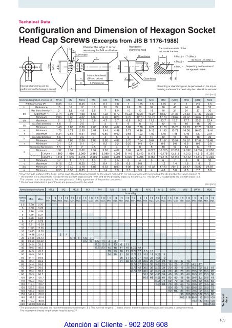
Technical DataConfiguration and Dimension of Hexagon SocketHead Cap Screws (Excerpts from JIS B 1176-1988)se120°(Min.)Internal chamfering can beperformed on the hexagon socket.dktKwChamfer the edge. It is notnecessary for M4 and below.Cone basedrdadssgIncomplete thread(2P and below)b (Reference)RoundnessNominal designation of screw (d) M1.6 M2 M2.5 M3 M4 M5 M6 M8 M10 M12 (M14) M16 (M18) M20Pitch of screw (P) 0.35 0.4 0.45 0.5 0.7 0.8 1 1.25 1.5 1.75 2 2 2.5 2.5b Reference 15 16 17 18 20 22 24 28 32 36 40 44 48 52Max. (Basic dimension)* 1 3 3.8 4.5 5.5 7 8.5 10 13 16 18 21 24 27 30dk Maximum * 2 3.14 3.98 4.68 5.68 7.22 8.72 10.22 13.27 16.27 18.27 21.33 24.33 27.33 30.33Minimum 2.86 3.62 4.32 5.32 6.78 8.28 9.78 12.73 15.73 17.73 20.67 23.67 26.67 29.67da Maximum 2 2.6 3.1 3.6 4.7 5.7 6.8 9.2 11.2 13.7 15.7 17.7 20.2 22.4dsMax. (Basic dimension) 1.6 2 2.5 3 4 5 6 8 10 12 14 16 18 20Minimum 1.46 1.86 2.36 2.86 3.82 4.82 5.82 7.78 9.78 11.73 13.73 15.73 17.73 19.67e Minimum 1.73 1.73 2.30 2.87 3.44 4.58 5.72 6.86 9.15 11.43 13.72 16.00 16.00 19.44f Maximum 0.34 0.51 0.51 0.51 0.60 0.60 0.68 1.02 1.02 1.45 1.45 1.45 1.87 2.04kMax. (Basic dimension) 1.6 2 2.5 3 4 5 6 8 10 12 14 16 18 20Minimum 1.46 1.86 2.36 2.86 3.82 4.82 5.70 7.64 9.64 11.57 13.57 15.57 17.57 19.48r Minimum 0.1 0.1 0.1 0.1 0.2 0.2 0.25 0.4 0.4 0.6 0.6 0.6 0.6 0.8Nominal disig. (Basic dimension) 1.5 1.5 2 2.5 3 4 5 6 8 10 12 14 14 17Minimum 1.52 1.52 2.02 2.52 3.02 4.02 5.02 6.02 8.025 10.025 12.032 14.032 14.032 17.050sColumn 1 1.560 1.560 2.060 2.580 3.080 4.095 5.140 6.140 8.175 10.175 12.212 14.212 14.212 17.230MaximumColumn 2 1.545 1.545 2.045 2.560 3.080 4.095 5.095 6.095 8.155 10.115 12.142 14.142 14.142 17.230t Minimum 0.7 1 1.1 1.3 2 2.5 3 4 5 6 7 8 9 10v Maximum 0.16 0.2 0.25 0.3 0.4 0.5 0.6 0.8 1 1.2 1.4 1.6 1.8 2dw Minimum 2.72 3.40 4.18 5.07 6.53 8.03 9.38 12.33 15.33 17.23 20.17 23.17 25.87 28.87w Minimum 0.55 0.55 0.85 1.15 1.4 1.9 2.3 3.3 4 4.8 5.8 6.8 7.7 8.6* Knurl the side surface of the head. In this case, the dk (Maximum) shall be the values marked *2. For side surfaces with no knurling, the dk shall be the values marked *1.* The column 1 of S (Maximum) is used for the strength class 8.8 and 10.9, and for the property class A2-50 and A2-70. The column 2 is applied to the strength class 12.9.The column 1 can be applied to the strength class 12.9 by agreement of the parties concerned.* The nominal diameters in parentheses are preferably not to be used.dkVVRounded orchamfered head45°(Max.)rdwChamferingThe maximum state of therad. under the headfrrdaf (Max.) = 1.7r (Max.)r (Max.) =r (Min.) =dsda (Max.) −ds (Max.)2Depending on the value ofthe appendix tableRounding or chamfering can be performed on the top orbearing surface of the head. Any burr should be removed.Unit [mm]Unit [mm]Nominal designation of screw M1.6 M2 M2.5 M3 M4 M5 M6 M8 M10 M12 (M14) M16 (M18) M20ll s and l gNominallengthMin.Max.l sMin.l gMax.l sMin.l gMax.l sMin.l gMax.l sMin.l gMax.l sMin.l gMax.l sMin.l gMax.2.5 2.30 2.703 2.80 3.204 3.76 4.245 4.76 5.246 5.76 6.248 7.71 8.2910 9.71 10.2912 11.65 12.3516 15.65 16.3520 19.58 20.42 2 425 24.58 25.42 5.75 8 4.5 730 29.58 30.42 9.5 12 6.5 10 4 835 34.5 35.5 11.5 15 9 13 6 1140 39.5 40.5 16.5 20 14 18 11 16 5.75 1245 44.5 45.5 19 23 16 21 10.75 17 5.5 1350 49.5 50.5 24 28 21 26 15.75 22 10.5 18 5.25 1455 54.4 55.6 26 31 20.75 27 15.5 23 10.25 1960 59.4 60.6 31 36 25.75 32 20.5 28 15.25 24 10 20 6 1665 64.4 65.6 30.75 37 25.5 33 20.25 29 15 25 11 21 4.5 1770 69.4 70.6 35.75 42 30.5 38 25.25 34 20 30 16 26 9.5 22 5.5 1880 79.4 80.6 45.75 52 40.5 48 35.25 44 30 40 26 36 19.5 32 15.5 2890 89.3 90.7 50.5 58 45.25 54 40 50 36 46 29.5 42 25.5 38100 99.3 100.7 60.5 68 55.25 64 50 60 46 56 39.5 52 35.5 48110 109.3 110.7 65.25 74 60 70 56 66 49.5 62 45.5 58120 119.3 120.7 75.25 84 70 80 66 76 59.5 72 55.5 68130 129.2 130.8 80 90 76 86 69.5 82 65.5 78140 139.2 140.8 90 100 86 96 79.5 92 75.5 88150 149.2 150.8 96 106 89.5 102 85.5 98160 159.2 160.8 106 116 99.5 112 95.5 108180 179.2 180.8 119.5 132 115.5 128200 199.05 200.95 135.5 148* The gray portion indicates the recommended nominal length ( l ). The nominal length ( l ) that is shorter than the dashed line position indicates a complete thread.The incomplete thread length under head is about 3P.l sMin.l gMax.l sMin.l gMax.l sMin.l gMax.l sMin.l gMax.l sMin.l gMax.l sMin.l gMax.l sMin.l gMax.l sMin.l gMax.TechnicaldataAtención al Cliente - 902 208 608103


