

COUPLINGS
COUPLINGS
COUPLINGS

Create successful ePaper yourself
Turn your PDF publications into a flip-book with our unique Google optimized e-Paper software.
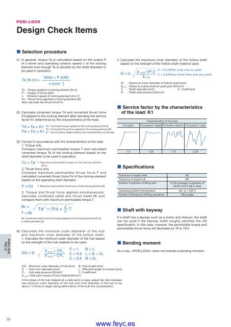
POSI-LOCKDesign Check Items• Selection procedure(1) In general, torque Ta is calculated based on the output Pof a driver and operating rotation speed n of the lockingelement even though Ta is decided by the shaft diameter tobe used in operation.Ta [N·m] =9550 × P [kW]n [min –1 ]Ta : Torque applied to locking element [N·m]P : Output of driver [kW]n : Rotation speed of locking element [min-1]Fa : Thrust force applied to locking element [N]Also calculate the thrust force Fa.(2) Calculate corrected torque Td and corrected thrust forceFd applied to the locking element after deciding the servicefactor K1 determined by the characteristics of the load.Td = Ta × K1Fd = Fa × K1Td : Corrected torque applied to the locking element [N·m]Fd : Corrected thrust force applied to the locking element [N]K1 : Service factor determined by the characteristics of the load2. Calculate the maximum inner diameter of the hollow shaftbased on the strength of the hollow shaft material used.di ≤ dδ 0.2N –2P 1 Cδ 0.2NC = 0.6 When only one is used.C = 0.8 When more than one are used.Di : Maximum inner diameter of hollow shaft [mm]δ 0.2N : Stress to hollow shaft at yield point [N/mm 2 ]d : Shaft diameter [mm] C : CoefficientP 1 : Shaft side pressure [N/mm 2 ]• Service factor by the characteristicsof the load: K1Characteristics of the loadConstant Fluctuation: Slight Fluctuation: Medium Fluctuation: LargePOSI LOCKPSL-G(3) Correct in accordance with the characteristics of the load.1. Torque onlyCompare maximum permissible torque T and calculatedcorrected torque Td of the locking element based on theshaft diameter to be used in operation.Tn ≥ Td T: Maximum permissible torque of the locking element[N·m]2. Thrust force onlyCompare maximum permissible thrust force F andcalculated corrected thrust force Fd of the locking elementbased on the operating shaft diameter.F ≥ Fd F: Maximum permissible thrust force of the locking element [N]3. Torque and thrust force applied simultaneously.Calculate combined radial and thrust loads Mr andcompare them with maximum permissible torque T.Mr =T ≥ MrTd 2 + Fd ×Mr: Combined radial and thrust loads applied to the locking element [N·m]d: Shaft diameter [m](4) Calculate the minimum outer diameter of the huband maximum inner diameter of the hollow shaft.1. Calculate the minimum outer diameter of the hub basedon the strength of the hub material to be used.DO ≥ Dδ 0.2N + CP 2δ 0.2N – CP 2d22C = 1 B = LC = 0.8 L < B < 2LC = 0.6 B ≥ 2L1.0 1.25 1.75 2.25• SpecificationsTolerance of target shaftTolerance of target hubSurface roughness of fi tting partOperating ambient temperatureNumber of fi tting and unfi tting operations• Shaft with keywayIf a shaft has a keyway such as a motor and reducer, the shaftcan be used if the keyway width roughly satisfies the JISspecification. In this case, however, the permissible torque andpermissible thrust force will decrease by 10 to 15%.• Bending momenth9H812.5S (average roughness ofcenter line 3.2a) or less-40 to +150°C100 cyclesAs a rule, does not tolerate a bending moment.DO : Minimum outer diameter of hub [mm] B : Hub length [mm]D : Hub inner diameter [mm]L : Effective length of contact [mm]P 2 : Hub side pressure [N/mm 2 ]C : Coeffi cientδ 0.2N : Yield point stress of hub material [N/mm 2 ]If the stress of the hub material at a yield point is large, adjust the ratio betweenthe minimum outer diameter of the hub and inner diameter of the hub to beabout 1.3 times or larger taking deformation of the hub into consideration.92www.feyc.es


