

COUPLINGS
COUPLINGS
COUPLINGS

Create successful ePaper yourself
Turn your PDF publications into a flip-book with our unique Google optimized e-Paper software.
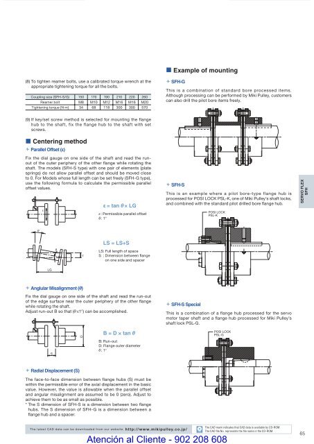
• Example of mounting(8) To tighten reamer bolts, use a calibrated torque wrench at theappropriate tightening torque for all the bolts.Coupling size (SFH-S/G) 150 170 190 210 220 260Reamer bolt M8 M10 M12 M16 M16 M20Tightening torque [N·m] 34 68 118 300 300 570 SFH-GThis is a combination of standard bore processed items.Although processing can be performed by Miki Pulley, customerscan also drill the pilot bore items freely.(9) If key/set screw method is selected for mounting the flangehub to the shaft, fix the flange hub to the shaft with setscrews.• Centering method Parallel Offset (ε)Fix the dial gauge on one side of the shaft and read the runoutof the outer periphery of the other fl ange while rotating theshaft. The models (SFH-S type) with one pair of elements (platesprings) do not allow parallel offset and should be moved closeto 0. For Models whose full length can be set freely (SFH-G type),use the following formula to calculate the permissible paralleloffset values.ε = tan θ × LGε : Permissible parallel offsetθ : 1° SFH-SThis is an example where a pilot bore-type flange hub isprocessed for POSI LOCK PSL-K, one of Miki Pulley’s shaft locks,and combined with the standard pilot drilled bore fl ange hub.POSI LOCKPSL-KSERVO FLEXSFHLS = LS+SLS: Full length of spaceS : Dimension between flangeon one side and spacerLG Anglular Misalignment (θ)Fix the dial gauge on one side of the shaft and read the run-outof the edge surface near the outer periphery of the other fl angewhile rotating the shaft.Adjust run-out B so that (θ ≤1°) can be accomplished. SFH-S SpecialThis is a combination of a flange hub processed for the servomotor taper shaft and a fl ange hub processed for Miki Pulley’sshaft lock PSL-G.SDB = D × tan θB: Run-outD: Flange outer diameterθ : 1°POSI LOCKPSL-G Radial Displacement (S)The face-to-face dimension between flange hubs (S) must bewithin the permissible error of the axial displacement in the basicvalue. However, the value is allowable when the parallel offsetand angular misalignment are assumed to be 0 (zero). Adjust toachieve them to be as small as possible.* The S dimension of SFH-S is a dimension between two flangehubs. The S dimension of SFH-G is a dimension between aflange hub and a spacer.The latest CAD data can be downloaded from our website. http://www.mikipulley.co.jp/COUPLING_E_56_65new.indd 65CADAtención al Cliente - 902 208 608The CAD mark indicates that CAD data is available by CD-ROM.The CAD fi le No. represents the fi le name in the CD-ROM.659/15/10 4:29 PM


