

1998 - Draper Laboratory
1998 - Draper Laboratory
1998 - Draper Laboratory
- No tags were found...

Create successful ePaper yourself
Turn your PDF publications into a flip-book with our unique Google optimized e-Paper software.
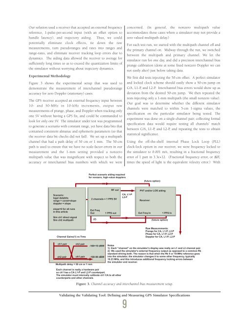
Our solution used a receiver that accepted an external frequencyreference, 1-pulse-per-second input (with an offset option tohandle latency), and trajectory aiding. Thus, we couldpotentially eliminate clock effects, tie down the rawmeasurements, turn pseudoranges and rates into ranges andrange-rates, and eliminate receiver tracking loop errors due todynamics. The aiding data allowed the receiver to average forsufficiently long times so as to exceed the quantization limits ofthe simulator without worrying about trajectory dynamics.Experimental MethodologyFigure 3 shows the experimental setup that was used todemonstrate the measurement of interchannel pseudorangeaccuracy for zero Doppler (stationary) cases.The GPS receiver accepted an external frequency input between10- and 50-MHz in 10-kHz increments, output rawmeasurements of prange, phase, and Doppler when tracking onlyone SV without having a GPS fix, and could be commanded tolook for only one SV. The simulator under test was programmedto generate a scenario with constant range, yet have data bits thatcontained consistent almanac and ephemeris parameters (so thatthe receiver data bit checks did not fail). We set up a multipathchannel that had a path delay of 50 cm or 1 mm. The 50-cmpath is used to ensure that we have no scale-factor errors in ourmeasurement and the 1-mm setting provided a nonzeromultipath value that was insignificant with respect to both theaccuracy or interchannel bias numbers with which we wereconcerned. (In general, the nonzero multipath valueaccommodates those cases where a simulator may not provide azero valued multipath delay.)For each test run, we started with the multipath channel off andthe primary channel on. Midway through the run, we switchedbetween the multipath and primary channel. We let thesimulator run for one day, and did a precision interchannel biasprange calibration (done at some fixed nonzero Doppler we cannot easily alter) just before taking data.We first did tests injecting the 50-cm offset. A perfect simulatorand locked clock scheme should easily show a 50-cm jump onC/A, L1-P, and L2-P. Interchannel bias errors would show up asdeviation from the desired 50-cm jump. We then repeated thetests injecting only a 1-mm multipath (the small nonzero value).Our goal was to determine whether the different simulatorchannels were matched to within 5-cm 1-sigma values, thespecification on the particular simulator being tested. Theexperiment was done on a single-channel pair; collecting formalspecification data would require testing all channels’ matchbetween C/A, L1-P, and L2-P, and repeating the tests to obtainstatistical significance.Using the off-the-shelf internal Phase Lock Loop (PLL)clock-lock option in our receiver, we were frequency locked tothe simulator to 0.001 m/s, resulting in a fractional frequencyerror of 1 part in 3.3e+12. (Fractional frequency error, or ∆f/f,times the speed of light is the equivalent velocity error.) WithPerfect scenario aiding requiredfor nonzero, high-value dopplers(future option)Scenario:legal databitsrange = const+slopedoppler = slopeRF out2 channels = 1 PPS SVCA, L1-PL2-PPVT and/or LOS aidingReceiver:slope=0 for all runsin this articleExt FreqOut1 PPS outExt Freq In1 PPS InSim ch1 direct signalSim ch2 multipath(2)(future option)Channel Gains(1) vs TimeRaw Measurements:Prange for CA, L1-P, L2-PPhase for CA, L1-P, L2-PDoppler for CA, L1-P, L2-Pch1 pair ch2 pair-160+10 dBWch2 pair ch1 pair -160-99 dBWMultipath delay = 50 cm or 1 mmNotes1): Each "channel" on the simulator's display was really an L1 and L2 channel pair.2): We used the simulator's external frequency output as opposed to a common Rbstandard driving both. The reason is that when the Rb 5 or 10-MHz reference goesinto the simulator, the simulator changes it to some other frequency, typically10.23 MHz, and this introduces additional frequency locking errors betweenthe simulator and receiver.Each channel is really a hardware pairso ch1 has a CA L1-P and L2-P counterpart.The simulator must internally calibrate ch1 CA to all othercounterparts and other channels.Figure 3. Channel accuracy and interchannel bias measurement setup.Validating the Validating Tool: Defining and Measuring GPS Simulator Specifications9


