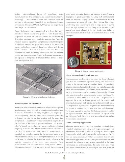
surface micromachining layers of polysilicon. Manymanufacturers are developing gyros and accelerometers using thistechnology. Their extremely small size combined with thestrength of silicon makes them ideal for very high-accelerationapplications. Between 3,000 and 10,000 devices can be producedon a single 5-in silicon wafer.<strong>Draper</strong> <strong>Laboratory</strong> has demonstrated a 4-deg/h bias drift,open-loop silicon tuning-fork gyroscope with folded beamsuspension in which the flexured masses are electrostaticallydriven into resonance with a comb-like structure (see Figure 2).Rotation is sensed capacitively along the axis normal to the planeof vibration. <strong>Draper</strong>’s first gyroscope is aimed at the automobilemarket and is being marketed through an alliance with BoeingNorth American. Devices with lower drift rates have beendeveloped for more demanding applications, such as autopilotcontrol and smart munitions. Future performance improvementsare expected to bring the performance of these devices to betterthan 0.1-deg/h bias drift.(proof mass, resonating flexure, and support structure) from asingle piece of quartz (see Figure 3). Using such techniques canresult in low-cost, highly reliable accelerometers with ameasurement accuracy of better than 100-µg bias error.Constructing this accelerometer from a single piece of quartzresults in high thermal stability, along with dynamic rangesapproaching those obtainable in the timekeeping industry.Silicon micromechanical resonator accelerometers are also beingdeveloped.Figure 3. Quartz resonant accelerometer.Silicon Micromechanical AccelerometersFigure 2. Micromechanical tuning-fork gyro.Resonating Beam AccelerometersResonant accelerometers (sometimes referred to as vibrating beamaccelerometers) have a principle of operation that is similar to thatof a violin. When the violin string is tightened, its frequency ofoperation goes up. Similarly, when the accelerometer proof massis loaded, one tine is put into tension and the other intocompression. These tines are excited continually at frequencies inthe hundreds of kilohertz range when unloaded. As a result,when “g” loaded, one tine frequency increases while the other tinefrequency decreases. This difference in frequency is a measure ofthe device’s acceleration. This form of accelerometer isessentially an open-loop device, in that the proof mass is notrebalanced to its center position during the application of a force.For accuracy, it relies on the scale-factor stability inherent in thematerial properties of the proof mass supports. Theseaccelerometers can be constructed using several differentfabrication techniques. One method is to etch the entire deviceMicromechanical accelerometers are either the force rebalancetype that use closed-loop capacitive sensing and electrostaticforcing, or the resonator type as described above. <strong>Draper</strong>’s forcerebalance micromechanical accelerometer is a typical example, inwhich the accelerometer is a monolithic silicon structure (i.e., noassembly of component parts) consisting of a torsional pendulumwith capacitive readout and electrostatic torquer (see Figure 4).This device is about 300 x 600 µm in size. The pendulum issupported by a pair of flexure pivots, and the readout andtorquing electrodes are built into the device beneath the tilt plate.The output of the angle sensor is integrated and then used to drivethe torquer to maintain the tilt plate in a fixed nulled position.The torque required to maintain this balance is proportional tothe input acceleration. Performance around 250-µg bias errorand 250 ppm of scale factor error have been achieved and furtherimprovements are expected.Future Technology ApplicationsSolid-state inertial sensors like those described previously havepotentially significant cost, size, and weight advantages overconventional instruments, which are resulting in a rethinking ofthe options for which such devices can be used in systems. Whilethere are many conventional military applications, there are alsomany newer applications that will emerge with the low cost andvery small size inherent in such sensors, particularly at the lowerperformance end of the spectrum. In nearly every case, whenthese newer solid-state inertial technologies have been evaluatedINS/GPS Technology Trends for Military Systems4
maintained in a rigid structure, whereas the FOG has its path infiber, making the FOG fundamentally much more susceptible toenvironmental effects such as temperature changes. Forcomparable performance applications, the selection between theFOG and the RLG will very likely depend on the scale-factorrequirements.Figure 4. Micromechanical pendulousrebalance accelerometer.against today’s technology, given comparable technicalrequirements, this new class of solid-state inertial sensorsbecomes the winner because the basis of selection is almostalways cost. A vision of the inertial instrument field for relevantmilitary applications for the near-term is shown in Tables 1 and 2for the gyro and accelerometer, respectively.The performance application region of about 0.01-deg/h bias driftfor gyros is expected to shift from current RLG applications toFOGs. The RLG is an excellent instrument, but itsmanufacturing is heavily dominated by precision machiningprocesses and alignment requirements, which force its costs toremain relatively high. It is quite possible that FOG performanceimprovements will allow applications in strategic missileapplications where the performance requirements exceed 0.001deg/h. However, one particular area the RLG is expected to retainits superiority is scale factor. The laser gyro has its optical pathTable 1. Near-term gyro requirements vs applications.The tactical lowest performance end of the gyro applicationspectrum will be dominated by micromechanical inertial sensors.These could be, for example, gyros and accelerometersphotolithographically constructed in silicon or quartz andsubsequently etched in very large numbers as a single batch. Themilitary market will push the development of these sensors forapplications such as “competent” and “smart” munitions, aircraftand missile autopilots, short time-of-flight tactical missileguidance, fire control systems, radar antenna motioncompensation, “smart skins” using embedded inertial sensors,multiple intelligent small projectiles such as flechettes or even“bullets,” and wafer-scale INS/GPS systems.The potential commercial market for micromechanical inertialsensors is orders of magnitude larger than any contemplatedmilitary market. The application of micromechanical gyrotechnology to the automobile industry is one case where, forexample, a true skid detector requires a measure of inertial rate inorder to operate successfully. Products designed for this industrymust be inexpensive and reliable, both characteristics ofsolid-state technology. Many other micromechanical inertialsensor applications exist for automobiles such as airbags, braking,leveling, and GPS-augmented navigation systems. Additionalcommercial applications can be found in products such ascamcorders, factory automation, general aviation, and medicalelectronics. The performance of the micromechanicalinstruments will likely continue to improve as more commercialapplications are found for this technology.Table 2. Near-term accelerometer requirements vs applications.σµ σINS/GPS Technology Trends for Military Systems5
- Page 2 and 3:
Letter from thePresident and CEO,Vi
- Page 4 and 5:
Information TechnologyMilton AdamsE
- Page 6 and 7:
BiographyMilton Adams has been at D
- Page 9 and 10: Figure 1 represents a functional de
- Page 11 and 12: Programs. In effect, these controll
- Page 13 and 14: Although the terminal area traffic
- Page 15 and 16: Table 2. ATFM performance evaluatio
- Page 17 and 18: In the experiments, a nominal capac
- Page 19 and 20: [3] Wambsganss, Michael C. “Colla
- Page 21 and 22: Guidance, Navigation, and Control A
- Page 23 and 24: A Control Lyapunov FunctionApproach
- Page 25 and 26: x( 0) ∈ X and w(t) ∈Wfor all t
- Page 27 and 28: (b) Select a quadratic RCLF V i (x)
- Page 29 and 30: at each grid point. In the case w 1
- Page 31 and 32: References[1] Ball, J.A. and A.J. v
- Page 33 and 34: Guidance, Navigation, and Control A
- Page 35 and 36: Relative and Differential GPSData T
- Page 37 and 38: The first term on the right in the
- Page 39 and 40: H R# δρ R,GPS -H A# δρ A,GPSThi
- Page 41 and 42: selection; and (3) shown that the a
- Page 43 and 44: Guidance, Navigation, and Control A
- Page 45 and 46: Segmentation of MR ImagesUsing Curv
- Page 47 and 48: (3)where ν now represents a contin
- Page 49 and 50: Experimental ResultsThe results of
- Page 51 and 52: Table 1. A summary of segmentation
- Page 53 and 54: Guidance, Navigation,and ControlJim
- Page 55 and 56: BiographyGeorge SchmidtGeorge Schmi
- Page 57: clock and ephemeris errors, as well
- Page 61 and 62: Table 5. “Typical” absolute GPS
- Page 63 and 64: performed, then the target location
- Page 65 and 66: tightly-coupled system, however, ca
- Page 67 and 68: Concluding RemarksRecent progress i
- Page 69 and 70: As real-time systems evolve into th
- Page 71 and 72: Advanced Fault-TolerantComputing fo
- Page 73 and 74: The Viking and Voyager were both in
- Page 75 and 76: Containment Regions (FCRs). There a
- Page 77 and 78: well as reversing the whole process
- Page 79 and 80: As real-time systems evolve into th
- Page 81 and 82: Automated Station-Keepingfor Satell
- Page 83 and 84: Figure 2. Minimum elevation angles
- Page 85 and 86: anomaly M and/or the ascending node
- Page 87 and 88: However, since optimization and rec
- Page 89 and 90: is maintained in the Northern Hemis
- Page 91 and 92: autonomy. It must have the ability
- Page 93 and 94: [31] Neelon, Joseph G., Jr., Paul J
- Page 95 and 96: Draper’s primary goal is to Drape
- Page 97 and 98: )Rotordynamic Modelingof an Activel
- Page 99 and 100: Eq. (9) becomes:λ[ R ] { Φ } = [
- Page 101 and 102: chosen to be 24, for a total of 48
- Page 103 and 104: InertialInstruments/MechanicalDesig
- Page 105 and 106: BiographyJeffrey Borenstein is curr
- Page 107 and 108: process step. Process information i
- Page 109 and 110:
Figure 4. Control chart for boron d
- Page 111 and 112:
References[1] Barbour, N., J. Conne
- Page 113 and 114:
Draper Laboratory continues to engi
- Page 115 and 116:
Validating the Validating Tool:Defi
- Page 117 and 118:
calculates miscellaneous terms, suc
- Page 119 and 120:
Table 1. Suggested specification sh
- Page 121 and 122:
User Accuracy as aFunction of Simul
- Page 123 and 124:
20-min averaging, this clock lockin
- Page 125 and 126:
Table 2. Sample high-level summary
- Page 127 and 128:
AcknowledgmentR.L. Greenspan, J.A.
- Page 129 and 130:
Systems IntegrationRich MartoranaPe
- Page 131 and 132:
BiographyAnthony Kourepenis is an A
- Page 133 and 134:
control is employed to maintain the
- Page 135 and 136:
Table 1. Summary of automotive yaw
- Page 137 and 138:
Resolution (60 Hz) deg/h10000000100
- Page 139 and 140:
References[1] Greiff, P., B. Boxenh
- Page 141 and 142:
Guidance, Navigation, and Control A
- Page 143 and 144:
An Integrated Safety AnalysisMethod
- Page 145 and 146:
Infrastructure ModelsSystemRequirem
- Page 147 and 148:
Figures 6 and 7 illustrate the bloc
- Page 149 and 150:
Notice that each flight track descr
- Page 151 and 152:
Table 7. Safety statistics at 1700-
- Page 153 and 154:
Guidance, Navigation, and Control A
- Page 155 and 156:
An Optimal Guidance Law forPlanetar
- Page 157 and 158:
Note that the states in the three d
- Page 159 and 160:
Crossrange (Kft)10090807060504030Cl
- Page 161 and 162:
The 1997 Charles StarkDraper PrizeT
- Page 163 and 164:
The 1997 Charles StarkDraper Prize1
- Page 165 and 166:
“Draper encourages its personnel
- Page 167 and 168:
Gimballed Vibrating GyroscopeHaving
- Page 169 and 170:
“Draper encourages its personnel
- Page 171 and 172:
Optical Source Isolator withPolariz
- Page 173 and 174:
“Draper encourages its personnel
- Page 175 and 176:
Hunting Suppressor forPolyphase Ele
- Page 177 and 178:
“Draper encourages its personnel
- Page 179 and 180:
Sensor Having an Off-Frequency Driv
- Page 181 and 182:
proof mass from transients and enha
- Page 183 and 184:
1997 Published PapersThe following
- Page 185 and 186:
monitoring of space structures and
- Page 187 and 188:
measured by kinematic degrees of fr
- Page 189 and 190:
i.e., what percent of the earth’s
- Page 191 and 192:
McConley, M. W.; Dahleh, M. A.; Fer
- Page 193 and 194:
unaffordable, or even misguided. Bu
- Page 195 and 196:
The Draper DistinguishedPerformance
- Page 197:
Educational Activitiesat Draper Lab