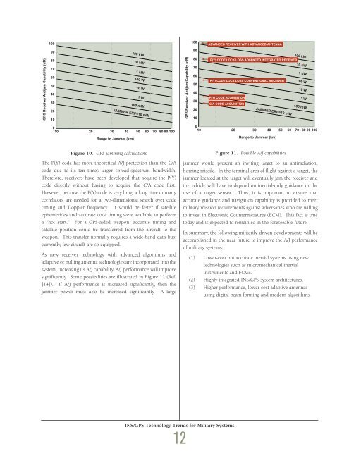
GPS Receiver Antijam Capability (dB)100908070605040302010100 kW10 kW1 kW100 W10 W1 W100 mWJAMMER ERP=10 mW010 20 30 40 50 60 70 80 90 100Range to Jammer (km)GPS Receiver Antijam Capability (dB)100908070605040302010ADVANCED RECEIVER WITH ADVANCED ANTENNAP(Y) CODE LOCK LOSS ADVANCED INTEGRATED RECEIVERP(Y) CODE LOCK LOSS CONVENTIONAL RECEIVERP(Y) CODE ACQUISITIONC/A CODE ACQUISITION100 kW10 kW1 kW100 W10 W1 W100 mWJAMMER ERP=10 mW010 20 30 40 50 60 70 80 90 100Range to Jammer (km)Figure 10. GPS jamming calculationsThe P(Y) code has more theoretical A/J protection than the C/Acode due to its ten times larger spread-spectrum bandwidth.Therefore, receivers have been developed that acquire the P(Y)code directly without having to acquire the C/A code first.However, because the P(Y) code is very long, a long time or manycorrelators are needed for a two-dimensional search over codetiming and Doppler frequency. It would be faster if satelliteephemerides and accurate code timing were available to performa “hot start.” For a GPS-aided weapon, accurate timing andsatellite position could be transferred from the aircraft to theweapon. This transfer normally requires a wide-band data bus;currently, few aircraft are so equipped.As new receiver technology with advanced algorithms andadaptive or nulling antenna technologies are incorporated into thesystem, increasing its A/J capability, A/J performance will improvesignificantly. Some possibilities are illustrated in Figure 11 (Ref.[14]). If A/J performance is increased significantly, then thejammer power must also be increased significantly. A largeFigure 11. Possible A/J capabilitiesjammer would present an inviting target to an antiradiation,homing missile. In the terminal area of flight against a target, thejammer located at the target will eventually jam the receiver andthe vehicle will have to depend on inertial-only guidance or theuse of a target sensor. Thus, it is important to ensure thataccurate guidance and navigation capability is provided to meetmilitary mission requirements against adversaries who are willingto invest in Electronic Countermeasures (ECM). This fact is truetoday and is expected to remain so in the foreseeable future.In summary, the following militarily-driven developments will beaccomplished in the near future to improve the A/J performanceof military systems:(1) Lower-cost but accurate inertial systems using newtechnologies such as micromechanical inertialinstruments and FOGs.(2) Highly integrated INS/GPS system architectures.(3) Higher-performance, lower-cost adaptive antennasusing digital beam forming and modern algorithms.INS/GPS Technology Trends for Military Systems12
Concluding RemarksRecent progress in INS/GPS technology has accelerated thepotential use of these integrated systems, while awareness has alsoincreased concerning vulnerabilities to jamming. In the nearfuture, improvements in accuracy in the broadcast GPS signalswill evolve to 1 m. Many uses will be found for this highaccuracy. In parallel, lower-cost inertial components will bedeveloped and they will also have improved accuracy. Highlyintegrated A/J architectures for INS/GPS systems will becomecommon, replacing avionics architectures based on functionalblack boxes where receivers and inertial systems are treated asstand-alone systems.Acknowledgments/Additional ReferencesThanks to Neil Barbour and John Elwell for assistance with thesection on Inertial Sensor Trends. A history of inertial navigationis given in Ref. [15] and the history of the GPS program is givenin Ref. [16].References[1] Barbour, N., J. Elwell, G. Schmidt, R. Setterlund, “InertialInstruments: Where to Now?,” <strong>Draper</strong> <strong>Laboratory</strong>,Cambridge, MA, May 1994. Presented at the 1st InternationalConference on Gyroscopic Technology, Elektropribor Institute,St. Petersburg, Russia, May 1994.[2] Barbour, N., K. Kumar, J. Elwell, “Emerging Low(er) CostInertial Sensors,” <strong>Draper</strong> <strong>Laboratory</strong> Report P-3399,Cambridge, MA, July 1994. Presented at the 22nd JointServices Data Exchange, Scottsdale, AZ, October 1994.[3] Snyder, S. et al., “INS/GPS Operational ConceptDemonstration (OCD) High Gear Program,” IEEE PLANSConference, April 1994, pp. 292-297.[4] National Research Council, The Global Positioning System - AShared National Asset, National Academy Press, Washington,D.C., 1995.[5] Butts, J. and C. Shank, “Navigation Message Correction Tables:A Proposal,” ION National Technical Meeting, January 1995,pp. 97-103.[6] Brottland, B. and C. Harris, “Navigation Message CorrectionTables: On Orbit Results,” ION 51st Annual Meeting, June1995, pp. 413-420.[7] Dargen, J. et al., “Exploitation of Differential GPS for GuidanceEnhancement (EDGE) High Gear Program,” NATO/AGARDMSP Meeting, Technologies for Precision Air Strike Operationsin Rapid Reaction and Localized Conflict Scenarios, Seville,Spain, October 1995.[8] Kelly, D. et al., “Navigation Performance Analysis for the EDGEProgram,” NATO/AGARD MSP Meeting, Technologies forPrecision Air Strike Operations in Rapid Reaction andLocalized Conflict Scenarios, Seville, Spain, October 1995.[9] Moeglein, M. et al., “Options for PPS Space Segment AccuracyEnhancement,” Navigation, Fall 1996, Vol. 43, No. 3, pp. 221-235.[10] Phillips, R. and G. Schmidt, “Relative and Differential GPS,” inNATO AGARD Lecture Series 207 on System Implications andInnovative Applications of Satellite Navigation, June 1996, pp.5.1-5.22.[11] Phillips, R. and G. Schmidt, “INS/GPS Integration,” in NATOAGARD Lecture Series 207 on System Implications andInnovative Applications of Satellite Navigation, June 1996, pp.9.1-9.18.[12] NAVSTAR-GPS Joint Program Office, NAVSTAR GPS UserEquipment, February 1991.[13] Mahmood, S. et al., “Analysis of Differential Global PositioningSystem (DGPS) Techniques and GPS Jamming on PrecisionGuided Munition (PGM) Performance,” NATO/AGARD MSPMeeting, Technologies for Precision Air Strike Operations inRapid Reaction and Localized Conflict Scenarios, Seville,Spain, October 1995.[14] Sklar, J., “GPS Capability Projections” in Defense Science Board1996 Summer Study Task Force on Tactics and Technology for21st Century Military Superiority, Vol. 3, October 1996, III.43-[15] <strong>Draper</strong>, C. S., “Origins of Inertial Navigation,” Journal ofGuidance and Control, Vol. 4, No. 5, 1981, pp. 449-463.[16] Parkinson, B., “Origins, Evolution, and Future of SatelliteNavigation,” Journal of Guidance, Control, and Dynamics, Vol.20, No. 1, 1997, pp. 11-25.INS/GPS Technology Trends for Military Systems13
- Page 2 and 3:
Letter from thePresident and CEO,Vi
- Page 4 and 5:
Information TechnologyMilton AdamsE
- Page 6 and 7:
BiographyMilton Adams has been at D
- Page 9 and 10:
Figure 1 represents a functional de
- Page 11 and 12:
Programs. In effect, these controll
- Page 13 and 14:
Although the terminal area traffic
- Page 15 and 16: Table 2. ATFM performance evaluatio
- Page 17 and 18: In the experiments, a nominal capac
- Page 19 and 20: [3] Wambsganss, Michael C. “Colla
- Page 21 and 22: Guidance, Navigation, and Control A
- Page 23 and 24: A Control Lyapunov FunctionApproach
- Page 25 and 26: x( 0) ∈ X and w(t) ∈Wfor all t
- Page 27 and 28: (b) Select a quadratic RCLF V i (x)
- Page 29 and 30: at each grid point. In the case w 1
- Page 31 and 32: References[1] Ball, J.A. and A.J. v
- Page 33 and 34: Guidance, Navigation, and Control A
- Page 35 and 36: Relative and Differential GPSData T
- Page 37 and 38: The first term on the right in the
- Page 39 and 40: H R# δρ R,GPS -H A# δρ A,GPSThi
- Page 41 and 42: selection; and (3) shown that the a
- Page 43 and 44: Guidance, Navigation, and Control A
- Page 45 and 46: Segmentation of MR ImagesUsing Curv
- Page 47 and 48: (3)where ν now represents a contin
- Page 49 and 50: Experimental ResultsThe results of
- Page 51 and 52: Table 1. A summary of segmentation
- Page 53 and 54: Guidance, Navigation,and ControlJim
- Page 55 and 56: BiographyGeorge SchmidtGeorge Schmi
- Page 57 and 58: clock and ephemeris errors, as well
- Page 59 and 60: maintained in a rigid structure, wh
- Page 61 and 62: Table 5. “Typical” absolute GPS
- Page 63 and 64: performed, then the target location
- Page 65: tightly-coupled system, however, ca
- Page 69 and 70: As real-time systems evolve into th
- Page 71 and 72: Advanced Fault-TolerantComputing fo
- Page 73 and 74: The Viking and Voyager were both in
- Page 75 and 76: Containment Regions (FCRs). There a
- Page 77 and 78: well as reversing the whole process
- Page 79 and 80: As real-time systems evolve into th
- Page 81 and 82: Automated Station-Keepingfor Satell
- Page 83 and 84: Figure 2. Minimum elevation angles
- Page 85 and 86: anomaly M and/or the ascending node
- Page 87 and 88: However, since optimization and rec
- Page 89 and 90: is maintained in the Northern Hemis
- Page 91 and 92: autonomy. It must have the ability
- Page 93 and 94: [31] Neelon, Joseph G., Jr., Paul J
- Page 95 and 96: Draper’s primary goal is to Drape
- Page 97 and 98: )Rotordynamic Modelingof an Activel
- Page 99 and 100: Eq. (9) becomes:λ[ R ] { Φ } = [
- Page 101 and 102: chosen to be 24, for a total of 48
- Page 103 and 104: InertialInstruments/MechanicalDesig
- Page 105 and 106: BiographyJeffrey Borenstein is curr
- Page 107 and 108: process step. Process information i
- Page 109 and 110: Figure 4. Control chart for boron d
- Page 111 and 112: References[1] Barbour, N., J. Conne
- Page 113 and 114: Draper Laboratory continues to engi
- Page 115 and 116: Validating the Validating Tool:Defi
- Page 117 and 118:
calculates miscellaneous terms, suc
- Page 119 and 120:
Table 1. Suggested specification sh
- Page 121 and 122:
User Accuracy as aFunction of Simul
- Page 123 and 124:
20-min averaging, this clock lockin
- Page 125 and 126:
Table 2. Sample high-level summary
- Page 127 and 128:
AcknowledgmentR.L. Greenspan, J.A.
- Page 129 and 130:
Systems IntegrationRich MartoranaPe
- Page 131 and 132:
BiographyAnthony Kourepenis is an A
- Page 133 and 134:
control is employed to maintain the
- Page 135 and 136:
Table 1. Summary of automotive yaw
- Page 137 and 138:
Resolution (60 Hz) deg/h10000000100
- Page 139 and 140:
References[1] Greiff, P., B. Boxenh
- Page 141 and 142:
Guidance, Navigation, and Control A
- Page 143 and 144:
An Integrated Safety AnalysisMethod
- Page 145 and 146:
Infrastructure ModelsSystemRequirem
- Page 147 and 148:
Figures 6 and 7 illustrate the bloc
- Page 149 and 150:
Notice that each flight track descr
- Page 151 and 152:
Table 7. Safety statistics at 1700-
- Page 153 and 154:
Guidance, Navigation, and Control A
- Page 155 and 156:
An Optimal Guidance Law forPlanetar
- Page 157 and 158:
Note that the states in the three d
- Page 159 and 160:
Crossrange (Kft)10090807060504030Cl
- Page 161 and 162:
The 1997 Charles StarkDraper PrizeT
- Page 163 and 164:
The 1997 Charles StarkDraper Prize1
- Page 165 and 166:
“Draper encourages its personnel
- Page 167 and 168:
Gimballed Vibrating GyroscopeHaving
- Page 169 and 170:
“Draper encourages its personnel
- Page 171 and 172:
Optical Source Isolator withPolariz
- Page 173 and 174:
“Draper encourages its personnel
- Page 175 and 176:
Hunting Suppressor forPolyphase Ele
- Page 177 and 178:
“Draper encourages its personnel
- Page 179 and 180:
Sensor Having an Off-Frequency Driv
- Page 181 and 182:
proof mass from transients and enha
- Page 183 and 184:
1997 Published PapersThe following
- Page 185 and 186:
monitoring of space structures and
- Page 187 and 188:
measured by kinematic degrees of fr
- Page 189 and 190:
i.e., what percent of the earth’s
- Page 191 and 192:
McConley, M. W.; Dahleh, M. A.; Fer
- Page 193 and 194:
unaffordable, or even misguided. Bu
- Page 195 and 196:
The Draper DistinguishedPerformance
- Page 197:
Educational Activitiesat Draper Lab