INS/GPS Technology Trendsfor Military SystemsGeorge T. Schmidt The Charles Stark <strong>Draper</strong> <strong>Laboratory</strong>, Inc.Based on the paper published in the Proceedings of the AIAA Guidance, Navigation, and Control ConferenceAbstractThis paper focuses on accuracy and other technology trends forinertial sensors, Global Positioning Systems (GPS), and integratedInertial Navigation System (INS)/GPS systems, includingconsiderations of jamming for military platforms and weaponsthat will lead to 1-m accuracy navigation systems of the future.For inertial sensors, trend-setting sensor technologies applicableto military systems will be described. A vision of the inertialsensor instrument field and inertial systems for militaryapplications for the next few decades is given. GPS-specified andobserved current accuracies are described, as well as plannedaccuracy improvements, intersatellite ranging, and “all-in-view”tracking. Uses of Relative and Differential GPS (RGPS and DGPS,respectively) are discussed. The trend toward highly integratedINS/GPS is described and the synergistic benefits are explored.Some examples of the effects of jamming are described, andexpected technology trends to improve system antijam capabilityare presented.IntroductionDuring the last 50 years, Inertial Navigation Systems (INS) haveprogressed from the crude electromechanical devices that guidedthe early V-2 rockets to the current solid-state devices that are inmany modern vehicles. The impetus for this significant progresscame during the ballistic missile programs of the 1960s, in whichthe need for high accuracy at ranges of thousands of kilometersusing autonomous navigation systems was apparent. By“autonomous” it is meant that no man-made signals from outsidethe vehicle are required to perform navigation. If no externalman-made signals are required, then an enemy cannot jam them.One of the early leaders in inertial navigation was theMassachusetts Institute of Technology (MIT) Instrumentation<strong>Laboratory</strong> (now <strong>Draper</strong> <strong>Laboratory</strong>), which was asked by the AirForce to develop inertial systems for the Thor and Titan missilesand by the Navy to develop an inertial system for the Polarismissile. This request was made after the <strong>Laboratory</strong> haddemonstrated the feasibility of autonomous all-inertial navigationfor aircraft in a series of flight tests with a system called SPIRE(Space Inertial Reference Equipment). The notable success ofthose early missile programs led to further application in aircraft,ships, missiles, and spacecraft such that inertial systems are nowalmost standard equipment in military and civilian navigationapplications.Inertial navigation systems do not indicate position perfectlybecause of errors in components (the gyroscopes andaccelerometers) and errors in the model of the gravity field thatthe INS implements. Those errors cause the error in indicatedposition to grow with time. The best autonomous militaryaircraft INS have errors that grow at the rate of about 500 m/h.For vehicles with short flight times, such errors might beacceptable. For longer-duration missions, it is usually necessaryto provide periodic measurements to the navigation system suchthat the errors caused by the inertial system are reset as close tozero as possible. Because GPS offers world-wide, highly accuratenavigation information at very low cost, it has rapidly become theprimary aid to be used in updating inertial systems, at thepenalty of using an aid that is quite vulnerable to jamming.Clearly, the ideal situation would be low-cost but highly accurateINS that can do all, or almost all, of the mission without usingGPS. 1The military has access to a specified accuracy of 21 m (95-percent probability) from the GPS Precise Positioning Service(PPS). This capability provides impressive world-wide navigationperformance, especially when multiple GPS measurements arecombined in a Kalman filter to update an INS on a militaryplatform or a weapon. The Kalman filter provides anopportunity to calibrate some of the GPS errors, such as satellite................................................................................1An INS must be initialized with information concerning position and velocity. A GPS receiver can determine its ownposition and velocity given enough time to do so. Thus, inertial navigation is a relative process; GPS is absolutenavigation in a given reference frame.INS/GPS Technology Trends for Military Systems2
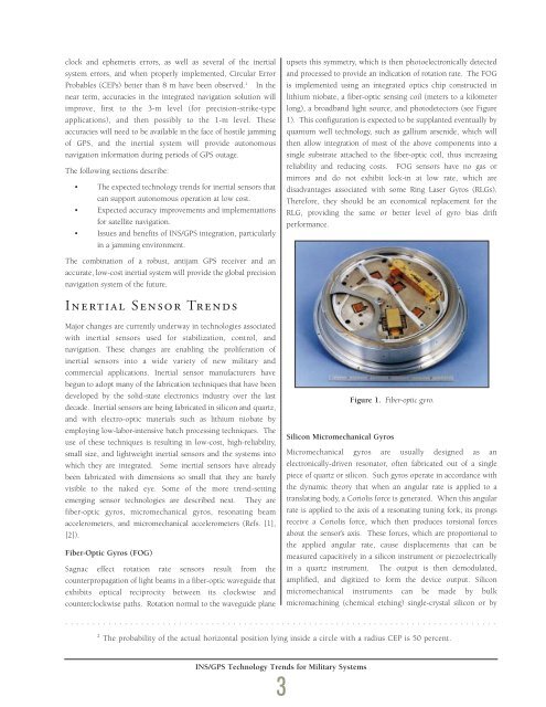
clock and ephemeris errors, as well as several of the inertialsystem errors, and when properly implemented, Circular ErrorProbables (CEPs) better than 8 m have been observed. 2 In thenear term, accuracies in the integrated navigation solution willimprove, first to the 3-m level (for precision-strike-typeapplications), and then possibly to the 1-m level. Theseaccuracies will need to be available in the face of hostile jammingof GPS, and the inertial system will provide autonomousnavigation information during periods of GPS outage.The following sections describe:• The expected technology trends for inertial sensors thatcan support autonomous operation at low cost.• Expected accuracy improvements and implementationsfor satellite navigation.• Issues and benefits of INS/GPS integration, particularlyin a jamming environment.upsets this symmetry, which is then photoelectronically detectedand processed to provide an indication of rotation rate. The FOGis implemented using an integrated optics chip constructed inlithium niobate, a fiber-optic sensing coil (meters to a kilometerlong), a broadband light source, and photodetectors (see Figure1). This configuration is expected to be supplanted eventually byquantum well technology, such as gallium arsenide, which willthen allow integration of most of the above components into asingle substrate attached to the fiber-optic coil, thus increasingreliability and reducing costs. FOG sensors have no gas ormirrors and do not exhibit lock-in at low rate, which aredisadvantages associated with some Ring Laser Gyros (RLGs).Therefore, they should be an economical replacement for theRLG, providing the same or better level of gyro bias driftperformance.The combination of a robust, antijam GPS receiver and anaccurate, low-cost inertial system will provide the global precisionnavigation system of the future.Inertial Sensor TrendsMajor changes are currently underway in technologies associatedwith inertial sensors used for stabilization, control, andnavigation. These changes are enabling the proliferation ofinertial sensors into a wide variety of new military andcommercial applications. Inertial sensor manufacturers havebegun to adopt many of the fabrication techniques that have beendeveloped by the solid-state electronics industry over the lastdecade. Inertial sensors are being fabricated in silicon and quartz,and with electro-optic materials such as lithium niobate byemploying low-labor-intensive batch processing techniques. Theuse of these techniques is resulting in low-cost, high-reliability,small size, and lightweight inertial sensors and the systems intowhich they are integrated. Some inertial sensors have alreadybeen fabricated with dimensions so small that they are barelyvisible to the naked eye. Some of the more trend-settingemerging sensor technologies are described next. They arefiber-optic gyros, micromechanical gyros, resonating beamaccelerometers, and micromechanical accelerometers (Refs. [1],[2]).Fiber-Optic Gyros (FOG)Sagnac effect rotation rate sensors result from thecounterpropagation of light beams in a fiber-optic waveguide thatexhibits optical reciprocity between its clockwise andcounterclockwise paths. Rotation normal to the waveguide planeFigure 1. Fiber-optic gyro.Silicon Micromechanical GyrosMicromechanical gyros are usually designed as anelectronically-driven resonator, often fabricated out of a singlepiece of quartz or silicon. Such gyros operate in accordance withthe dynamic theory that when an angular rate is applied to atranslating body, a Coriolis force is generated. When this angularrate is applied to the axis of a resonating tuning fork, its prongsreceive a Coriolis force, which then produces torsional forcesabout the sensor’s axis. These forces, which are proportional tothe applied angular rate, cause displacements that can bemeasured capacitively in a silicon instrument or piezoelectricallyin a quartz instrument. The output is then demodulated,amplified, and digitized to form the device output. Siliconmicromechanical instruments can be made by bulkmicromachining (chemical etching) single-crystal silicon or by................................................................................2The probability of the actual horizontal position lying inside a circle with a radius CEP is 50 percent.INS/GPS Technology Trends for Military Systems3
- Page 2 and 3:
Letter from thePresident and CEO,Vi
- Page 4 and 5:
Information TechnologyMilton AdamsE
- Page 6 and 7: BiographyMilton Adams has been at D
- Page 9 and 10: Figure 1 represents a functional de
- Page 11 and 12: Programs. In effect, these controll
- Page 13 and 14: Although the terminal area traffic
- Page 15 and 16: Table 2. ATFM performance evaluatio
- Page 17 and 18: In the experiments, a nominal capac
- Page 19 and 20: [3] Wambsganss, Michael C. “Colla
- Page 21 and 22: Guidance, Navigation, and Control A
- Page 23 and 24: A Control Lyapunov FunctionApproach
- Page 25 and 26: x( 0) ∈ X and w(t) ∈Wfor all t
- Page 27 and 28: (b) Select a quadratic RCLF V i (x)
- Page 29 and 30: at each grid point. In the case w 1
- Page 31 and 32: References[1] Ball, J.A. and A.J. v
- Page 33 and 34: Guidance, Navigation, and Control A
- Page 35 and 36: Relative and Differential GPSData T
- Page 37 and 38: The first term on the right in the
- Page 39 and 40: H R# δρ R,GPS -H A# δρ A,GPSThi
- Page 41 and 42: selection; and (3) shown that the a
- Page 43 and 44: Guidance, Navigation, and Control A
- Page 45 and 46: Segmentation of MR ImagesUsing Curv
- Page 47 and 48: (3)where ν now represents a contin
- Page 49 and 50: Experimental ResultsThe results of
- Page 51 and 52: Table 1. A summary of segmentation
- Page 53 and 54: Guidance, Navigation,and ControlJim
- Page 55: BiographyGeorge SchmidtGeorge Schmi
- Page 59 and 60: maintained in a rigid structure, wh
- Page 61 and 62: Table 5. “Typical” absolute GPS
- Page 63 and 64: performed, then the target location
- Page 65 and 66: tightly-coupled system, however, ca
- Page 67 and 68: Concluding RemarksRecent progress i
- Page 69 and 70: As real-time systems evolve into th
- Page 71 and 72: Advanced Fault-TolerantComputing fo
- Page 73 and 74: The Viking and Voyager were both in
- Page 75 and 76: Containment Regions (FCRs). There a
- Page 77 and 78: well as reversing the whole process
- Page 79 and 80: As real-time systems evolve into th
- Page 81 and 82: Automated Station-Keepingfor Satell
- Page 83 and 84: Figure 2. Minimum elevation angles
- Page 85 and 86: anomaly M and/or the ascending node
- Page 87 and 88: However, since optimization and rec
- Page 89 and 90: is maintained in the Northern Hemis
- Page 91 and 92: autonomy. It must have the ability
- Page 93 and 94: [31] Neelon, Joseph G., Jr., Paul J
- Page 95 and 96: Draper’s primary goal is to Drape
- Page 97 and 98: )Rotordynamic Modelingof an Activel
- Page 99 and 100: Eq. (9) becomes:λ[ R ] { Φ } = [
- Page 101 and 102: chosen to be 24, for a total of 48
- Page 103 and 104: InertialInstruments/MechanicalDesig
- Page 105 and 106: BiographyJeffrey Borenstein is curr
- Page 107 and 108:
process step. Process information i
- Page 109 and 110:
Figure 4. Control chart for boron d
- Page 111 and 112:
References[1] Barbour, N., J. Conne
- Page 113 and 114:
Draper Laboratory continues to engi
- Page 115 and 116:
Validating the Validating Tool:Defi
- Page 117 and 118:
calculates miscellaneous terms, suc
- Page 119 and 120:
Table 1. Suggested specification sh
- Page 121 and 122:
User Accuracy as aFunction of Simul
- Page 123 and 124:
20-min averaging, this clock lockin
- Page 125 and 126:
Table 2. Sample high-level summary
- Page 127 and 128:
AcknowledgmentR.L. Greenspan, J.A.
- Page 129 and 130:
Systems IntegrationRich MartoranaPe
- Page 131 and 132:
BiographyAnthony Kourepenis is an A
- Page 133 and 134:
control is employed to maintain the
- Page 135 and 136:
Table 1. Summary of automotive yaw
- Page 137 and 138:
Resolution (60 Hz) deg/h10000000100
- Page 139 and 140:
References[1] Greiff, P., B. Boxenh
- Page 141 and 142:
Guidance, Navigation, and Control A
- Page 143 and 144:
An Integrated Safety AnalysisMethod
- Page 145 and 146:
Infrastructure ModelsSystemRequirem
- Page 147 and 148:
Figures 6 and 7 illustrate the bloc
- Page 149 and 150:
Notice that each flight track descr
- Page 151 and 152:
Table 7. Safety statistics at 1700-
- Page 153 and 154:
Guidance, Navigation, and Control A
- Page 155 and 156:
An Optimal Guidance Law forPlanetar
- Page 157 and 158:
Note that the states in the three d
- Page 159 and 160:
Crossrange (Kft)10090807060504030Cl
- Page 161 and 162:
The 1997 Charles StarkDraper PrizeT
- Page 163 and 164:
The 1997 Charles StarkDraper Prize1
- Page 165 and 166:
“Draper encourages its personnel
- Page 167 and 168:
Gimballed Vibrating GyroscopeHaving
- Page 169 and 170:
“Draper encourages its personnel
- Page 171 and 172:
Optical Source Isolator withPolariz
- Page 173 and 174:
“Draper encourages its personnel
- Page 175 and 176:
Hunting Suppressor forPolyphase Ele
- Page 177 and 178:
“Draper encourages its personnel
- Page 179 and 180:
Sensor Having an Off-Frequency Driv
- Page 181 and 182:
proof mass from transients and enha
- Page 183 and 184:
1997 Published PapersThe following
- Page 185 and 186:
monitoring of space structures and
- Page 187 and 188:
measured by kinematic degrees of fr
- Page 189 and 190:
i.e., what percent of the earth’s
- Page 191 and 192:
McConley, M. W.; Dahleh, M. A.; Fer
- Page 193 and 194:
unaffordable, or even misguided. Bu
- Page 195 and 196:
The Draper DistinguishedPerformance
- Page 197:
Educational Activitiesat Draper Lab


