

1998 - Draper Laboratory
1998 - Draper Laboratory
1998 - Draper Laboratory
- No tags were found...

You also want an ePaper? Increase the reach of your titles
YUMPU automatically turns print PDFs into web optimized ePapers that Google loves.
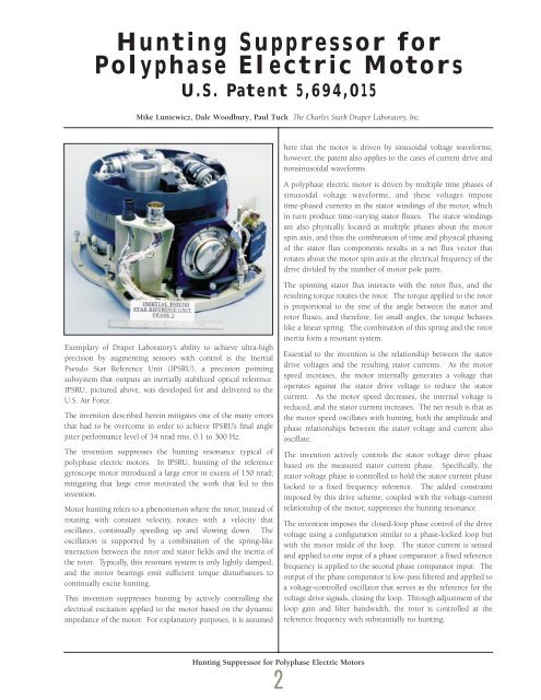
Hunting Suppressor forPolyphase Electric MotorsU.S. Patent 5,694,015Mike Luniewicz, Dale Woodbury, Paul Tuck The Charles Stark <strong>Draper</strong> <strong>Laboratory</strong>, Inc.here that the motor is driven by sinusoidal voltage waveforms;however, the patent also applies to the cases of current drive andnonsinusoidal waveforms.A polyphase electric motor is driven by multiple time phases ofsinusoidal voltage waveforms, and these voltages imposetime-phased currents in the stator windings of the motor, whichin turn produce time-varying stator fluxes. The stator windingsare also physically located at multiple phases about the motorspin axis, and thus the combination of time and physical phasingof the stator flux components results in a net flux vector thatrotates about the motor spin axis at the electrical frequency of thedrive divided by the number of motor pole pairs.Exemplary of <strong>Draper</strong> <strong>Laboratory</strong>’s ability to achieve ultra-highprecision by augmenting sensors with control is the InertialPseudo Star Reference Unit (IPSRU), a precision pointingsubsystem that outputs an inertially stabilized optical reference.IPSRU, pictured above, was developed for and delivered to theU.S. Air Force.The invention described herein mitigates one of the many errorsthat had to be overcome in order to achieve IPSRU’s final anglejitter performance level of 34 nrad rms, 0.1 to 300 Hz.The invention suppresses the hunting resonance typical ofpolyphase electric motors. In IPSRU, hunting of the referencegyroscope motor introduced a large error in excess of 150 nrad;mitigating that large error motivated the work that led to thisinvention.Motor hunting refers to a phenomenon where the rotor, instead ofrotating with constant velocity, rotates with a velocity thatoscillates, continually speeding up and slowing down. Theoscillation is supported by a combination of the spring-likeinteraction between the rotor and stator fields and the inertia ofthe rotor. Typically, this resonant system is only lightly damped,and the motor bearings emit sufficient torque disturbances tocontinually excite hunting.This invention suppresses hunting by actively controlling theelectrical excitation applied to the motor based on the dynamicimpedance of the motor. For explanatory purposes, it is assumedThe spinning stator flux interacts with the rotor flux, and theresulting torque rotates the rotor. The torque applied to the rotoris proportional to the sine of the angle between the stator androtor fluxes, and therefore, for small angles, the torque behaveslike a linear spring. The combination of this spring and the rotorinertia form a resonant system.Essential to the invention is the relationship between the statordrive voltages and the resulting stator currents. As the motorspeed increases, the motor internally generates a voltage thatoperates against the stator drive voltage to reduce the statorcurrent. As the motor speed decreases, the internal voltage isreduced, and the stator current increases. The net result is that asthe motor speed oscillates with hunting, both the amplitude andphase relationships between the stator voltage and current alsooscillate.The invention actively controls the stator voltage drive phasebased on the measured stator current phase. Specifically, thestator voltage phase is controlled to hold the stator current phaselocked to a fixed frequency reference. The added constraintimposed by this drive scheme, coupled with the voltage-currentrelationship of the motor, suppresses the hunting resonance.The invention imposes the closed-loop phase control of the drivevoltage using a configuration similar to a phase-locked loop butwith the motor inside of the loop. The stator current is sensedand applied to one input of a phase comparator; a fixed referencefrequency is applied to the second phase comparator input. Theoutput of the phase comparator is low-pass filtered and applied toa voltage-controlled oscillator that serves as the reference for thevoltage drive signals, closing the loop. Through adjustment of theloop gain and filter bandwidth, the rotor is controlled at thereference frequency with substantially no hunting.Hunting Suppressor for Polyphase Electric Motors2


