

1998 - Draper Laboratory
1998 - Draper Laboratory
1998 - Draper Laboratory
- No tags were found...

Create successful ePaper yourself
Turn your PDF publications into a flip-book with our unique Google optimized e-Paper software.
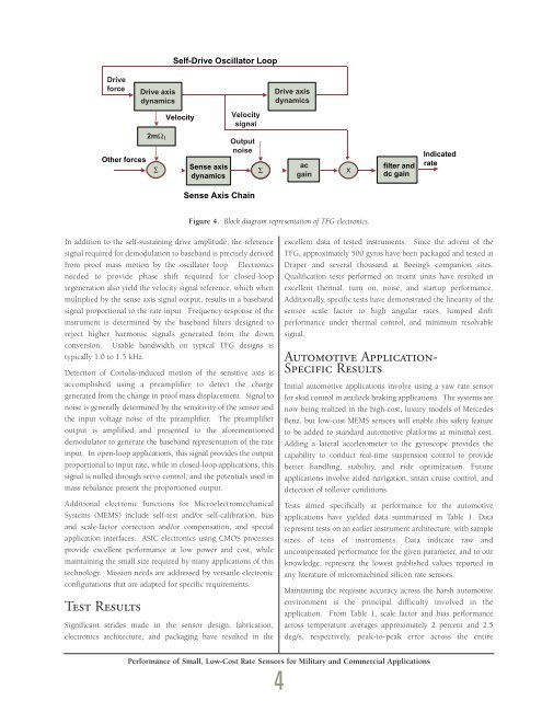
DriveforceOther forcesDrive axisdynamics2mΩISelf-Drive Oscillator LoopVelocitySense axisdynamicsVelocitysignalOutputnoiseSense Axis ChainDrive axisdynamicsac∑ Xgainfilter anddc gainIndicatedrateFigure 4. Block diagram representation of TFG electronics.In addition to the self-sustaining drive amplitude, the referencesignal required for demodulation to baseband is precisely derivedfrom proof mass motion by the oscillator loop. Electronicsneeded to provide phase shift required for closed-loopregeneration also yield the velocity signal reference, which whenmultiplied by the sense axis signal output, results in a basebandsignal proportional to the rate input. Frequency response of theinstrument is determined by the baseband filters designed toreject higher harmonic signals generated from the downconversion. Usable bandwidth on typical TFG designs istypically 1.0 to 1.5 kHz.Detection of Coriolis-induced motion of the sensitive axis isaccomplished using a preamplifier to detect the chargegenerated from the change in proof mass displacement. Signal tonoise is generally determined by the sensitivity of the sensor andthe input voltage noise of the preamplifier. The preamplifieroutput is amplified and presented to the aforementioneddemodulator to generate the baseband representation of the rateinput. In open-loop applications, this signal provides the outputproportional to input rate, while in closed-loop applications, thissignal is nulled through servo control, and the potentials used inmass rebalance present the proportioned output.Additional electronic functions for MicroelectromechanicalSystems (MEMS) include self-test and/or self-calibration, biasand scale-factor correction and/or compensation, and specialapplication interfaces. ASIC electronics using CMOS processesprovide excellent performance at low power and cost, whilemaintaining the small size required by many applications of thistechnology. Mission needs are addressed by versatile electronicconfigurations that are adapted for specific requirements.Test ResultsSignificant strides made in the sensor design, fabrication,electronics architecture, and packaging have resulted in theexcellent data of tested instruments. Since the advent of theTFG, approximately 500 gyros have been packaged and tested at<strong>Draper</strong> and several thousand at Boeing’s companion sites.Qualification tests performed on recent units have resulted inexcellent thermal, turn on, noise, and startup performance.Additionally, specific tests have demonstrated the linearity of thesensor scale factor to high angular rates, lumped driftperformance under thermal control, and minimum resolvablesignal.Automotive Application-Specific ResultsInitial automotive applications involve using a yaw rate sensorfor skid control in antilock braking applications. The systems arenow being realized in the high-cost, luxury models of MercedesBenz, but low-cost MEMS sensors will enable this safety featureto be added to standard automotive platforms at minimal cost.Adding a lateral accelerometer to the gyroscope provides thecapability to conduct real-time suspension control to providebetter handling, stability, and ride optimization. Futureapplications involve aided navigation, smart cruise control, anddetection of rollover conditions.Tests aimed specifically at performance for the automotiveapplications have yielded data summarized in Table 1. Datarepresent tests on an earlier instrument architecture, with samplesizes of tens of instruments. Data indicate raw anduncompensated performance for the given parameter, and to ourknowledge, represent the lowest published values reported inany literature of micromachined silicon rate sensors.Maintaining the requisite accuracy across the harsh automotiveenvironment is the principal difficulty involved in theapplication. From Table 1, scale factor and bias performanceacross temperature averages approximately 2 percent and 2.5deg/s, respectively, peak-to-peak error across the entirePerformance of Small, Low-Cost Rate Sensors for Military and Commercial Applications4


