E - VAE ProSys sro
E - VAE ProSys sro
E - VAE ProSys sro

You also want an ePaper? Increase the reach of your titles
YUMPU automatically turns print PDFs into web optimized ePapers that Google loves.
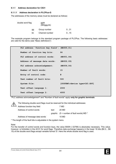
6.1.1 Address declaration for CS316.1.1.1 Address declaration in PLCPlus-GThe addresses of the memory areas must be declared as follows:double word flagggkk(MDggg,kk)gg Group number 0...31kk Channel number 0...15The example program belongs to the standard program package of PLCPlus. The following basic addressesare valid for the demo (see "Basic definitions"):PLC address 'function key field': (MD000,01)Number of function key bits: 64PLC address of control words:Address of message data words:PLC address acknowledgement:(MD001,04)(MD002,09)(MD006,04)Number of fault words: 15Entry of control code: #Text number of fault bits: 500System file:[SYSTEM\CS3.SDT]Text offset language 1: 2000Text offset language 2: 4000"PLC address acknowledgement" and "Number of fault words" apply only for graphic terminalsThe following double word flags must be reserved for the individual addresses:Address function key field7 MDAddress of control words text 20 MDgraphic (5 + number of fault words) MD *Address of message data words10 MD* The length of the fault bits is adjustable in the system menuNote:For the transfer of control words and function keys, the value 8000h (-32768) is absolutely necessary. This value,however, is forbidden in the AC31 for word flags. Therefore data exchange happens in the lower 16 bits (Bit 0... Bit15) of the double word flags except variable format 'D'. Here the whole double word flag is used.Process display and control/ Device Manual/ Issue: 07.0191E