- Page 1 and 2: INSTRUCTION MANUALDUAL BAND FM TRAN
- Page 3 and 4: PRECAUTIONSRWARNING RF EXPOSURE! Th
- Page 5 and 6: TABLE OF CONTENTS12FOREWORD .......
- Page 7 and 8: 13 MENU SCREEN OPERATION ..........
- Page 9 and 10: QUICK REFERENCE GUIDED LocationSele
- Page 11 and 12: QUICK REFERENCE GUIDED Optional GPS
- Page 13 and 14: QUICK REFERENCE GUIDEwAttach the re
- Page 15 and 16: QUICK REFERENCE GUIDED DC power sup
- Page 17 and 18: QUICK REFERENCE GUIDE■ Your first
- Page 19 and 20: QUICK REFERENCE GUIDE■ Repeater o
- Page 21 and 22: QUICK REFERENCE GUIDEUsing the HM-1
- Page 23 and 24: PANEL DESCRIPTION1yuiLeft band*The
- Page 25 and 26: PANEL DESCRIPTION1➥ During DV* (D
- Page 27 and 28: PANEL DESCRIPTION1@3@4@2FREQUENCY M
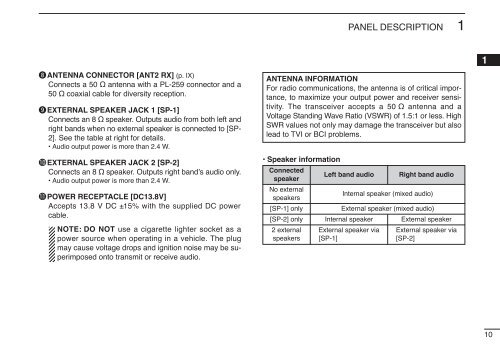
- Page 29: PANEL DESCRIPTION1D Function guide
- Page 33 and 34: PANEL DESCRIPTION1■ Microphone ke
- Page 35 and 36: PANEL DESCRIPTION1■ Optional Micr
- Page 37 and 38: SETTING A FREQUENCY2BANKY/Zz Push [
- Page 39 and 40: SETTING A FREQUENCY2■ Tuning step
- Page 41 and 42: BASIC OPERATION3■ ReceivingqSet t
- Page 43 and 44: BASIC OPERATION3■ Squelch attenua
- Page 45 and 46: BASIC OPERATION3■ Sub-band mute/b
- Page 47 and 48: BASIC OPERATION3When diversity oper
- Page 49 and 50: BASIC OPERATION3D Single sweepqSet
- Page 51 and 52: REPEATER OPERATION4■ Accessing a
- Page 53 and 54: REPEATER OPERATION4■ Subaudible t
- Page 55 and 56: REPEATER OPERATION4■ Offset frequ
- Page 57 and 58: DV MODE OPERATION (Optional UT-123
- Page 59 and 60: DV MODE OPERATION (Optional UT-123
- Page 61 and 62: DV MODE OPERATION (Optional UT-123
- Page 63 and 64: DV MODE OPERATION (Optional UT-123
- Page 65 and 66: DV MODE OPERATION (Optional UT-123
- Page 67 and 68: DV MODE OPERATION (Optional UT-123
- Page 69 and 70: DV MODE OPERATION (Optional UT-123
- Page 71 and 72: DV MODE OPERATION (Optional UT-123
- Page 73 and 74: DV MODE OPERATION (Optional UT-123
- Page 75 and 76: DV MODE OPERATION (Optional UT-123
- Page 77 and 78: DV MODE OPERATION (Optional UT-123
- Page 79 and 80: DV MODE OPERATION (Optional UT-123
- Page 81 and 82:
MEMORY MODE OPERATION6■ General d
- Page 83 and 84:
MEMORY MODE OPERATION6D Programming
- Page 85 and 86:
MEMORY MODE OPERATION6■ Memory ba
- Page 87 and 88:
MEMORY MODE OPERATION6[EXAMPLE]: Pr
- Page 89 and 90:
MEMORY MODE OPERATION6D Memory/call
- Page 91 and 92:
MEMORY MODE OPERATION6■ Erasing/t
- Page 93 and 94:
CALL CHANNEL OPERATION7■ Programm
- Page 95 and 96:
SCAN OPERATION8■ Scan start/stopD
- Page 97 and 98:
SCAN OPERATION8D Programming scan e
- Page 99 and 100:
SCAN OPERATION8■ Skip channel set
- Page 101 and 102:
PRIORITY WATCH9■ Priority watch o
- Page 103 and 104:
DTMF MEMORY ENCODER10■ Transmitti
- Page 105 and 106:
DTMF MEMORY ENCODER10■ DTMF speed
- Page 107 and 108:
TONE SQUELCH AND POCKET BEEP11D Rev
- Page 109 and 110:
TONE SQUELCH AND POCKET BEEP11■ D
- Page 111 and 112:
TONE SQUELCH AND POCKET BEEP11■ D
- Page 113 and 114:
PAGER/CODE SQUELCH12D Code programm
- Page 115 and 116:
PAGER/CODE SQUELCH12• PERSONAL CA
- Page 117 and 118:
MENU SCREEN OPERATION13■ Menu lis
- Page 119 and 120:
MENU SCREEN OPERATION13D SOUNDSITEM
- Page 121 and 122:
MENU SCREEN OPERATION13D Squelch de
- Page 123 and 124:
MENU SCREEN OPERATION13D Repeater c
- Page 125 and 126:
MENU SCREEN OPERATION13■ DUP/ TON
- Page 127 and 128:
MENU SCREEN OPERATION13D Opening lo
- Page 129 and 130:
MENU SCREEN OPERATION13■ DV GPS i
- Page 131 and 132:
MENU SCREEN OPERATION13D Alarm area
- Page 133 and 134:
MENU SCREEN OPERATION13D GPS-A symb
- Page 135 and 136:
OTHER FUNCTIONS14■ All resetThe f
- Page 137 and 138:
OTHER FUNCTIONS14D Cloning using a
- Page 139 and 140:
OTHER FUNCTIONS14D 1200 bps packet
- Page 141 and 142:
OTHER FUNCTIONS14D Adjusting the tr
- Page 143 and 144:
GPS/GPS-A OPERATION15yPush [BACK](V
- Page 145 and 146:
GPS/GPS-A OPERATION15o Rotate [DIAL
- Page 147 and 148:
GPS/GPS-A OPERATION15D RX GPS messa
- Page 149 and 150:
GPS/GPS-A OPERATION15■ GPS-A oper
- Page 151 and 152:
MAINTENANCE16PROBLEM POSSIBLE CAUSE
- Page 153 and 154:
SPECIFICATIONS AND OPTIONS17■ Spe
- Page 155 and 156:
SPECIFICATIONS AND OPTIONS17OPC-171
- Page 157 and 158:
ABOUT CE18Versions of the IC-E2820
- Page 159 and 160:
MEMO138
- Page 161 and 162:
MEMO140
- Page 163 and 164:
MEMO142


