Untitled - Technische Universiteit Eindhoven
Untitled - Technische Universiteit Eindhoven
Untitled - Technische Universiteit Eindhoven
- No tags were found...

Create successful ePaper yourself
Turn your PDF publications into a flip-book with our unique Google optimized e-Paper software.
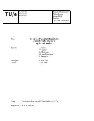
122 8. Model of reactive transport of an oil-soluble chemical in porous media8.4.2 Case A. Batch injection: exampleThe results of two of the simulations for case A are discussed first. We consider the case offast injection (Q = 1 ml min −1 ) versus slow injection (Q = 0.02 ml min −1 ). The amountof oil/TMOS mixture is two pore volumes (PV). The diffusion constant D is 10 −10 m 2s −1 . The interaction parameter ε 0 is equal to 5×10 3 J mol −1 K −1 and a = 4 (the latter isfour times higher than the parameter α used in the bulk model due to a different scalingin Eq. 8.17). The reaction constant k is based on the reaction constants determined inthe bulk experiments (see Chapter 4), i.e. k = 0.323×10 −3 s −1 (which corresponds to theexperiment without buffer). The total simulation time is 20 hours.The water saturation profiles are shown in Figure 8.3. As the TMOS solution isinjected the TMOS starts to partition between the oleic and aqueous phase in which itreacts to form methanol and silicic acid. Due to the mass transfer the saturation S wincreases and S o decreases. The amount of mixture exceeds (1 - S wi ) × 1 PV and duringinjection not all TMOS transfers instantly from the oleic to the aqueous phase. Therefore,some of the TMOS solution is produced at the outlet between t = 0 and t = t s . Given acertain reaction constant k and amount of PV injected, the flow rate Q has a significanteffect on the degree of change of the S w profiles, as can be observed in Figure 8.3. In casethe injection is relatively fast compared to the reaction rate, the injection of the mixtureresults in uniform S w profiles which increase gradually in the course of time during shut-inup to S w ≈ 0.42. However, in case the injection is relatively slow compared to the reactionrate, the S w profiles during injection start to develop a non-uniform and almost front-likebehavior towards the outlet. During shut-in the ongoing mass transfer of TMOS resultsin uniform S w profiles after several hours. The final saturation is however much higher(S w ≈ 0.48) compared to that in the fast injection case.0.50.50.40.4S w[-]0.30.2t=0timeS w[-]0.30.2t=0time0.10.10-0.03 -0.02 -0.01 0 0.01 0.02 0.03z [m]0-0.03 -0.02 -0.01 0 0.01 0.02 0.03z [m]Fig. 8.3: Water saturation profiles in the example simulations of Case A. Two PV of TMOS/oilwere injected between t = 0 and t = t s . Initially, S w = S wi . The time step betweendifferent solid curves is 0.8 hours. The dashed curve is the saturation profile at t =t s . The reaction constant is k = 0.323×10 −3 s −1 . (left) Q = 1 ml min −1 . (right) Q= 0.02 ml min −1 .Of main interest is the amount of silicic acid which is formed, since this indicates