Untitled - Technische Universiteit Eindhoven
Untitled - Technische Universiteit Eindhoven
Untitled - Technische Universiteit Eindhoven
- No tags were found...

You also want an ePaper? Increase the reach of your titles
YUMPU automatically turns print PDFs into web optimized ePapers that Google loves.
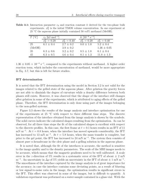
38 3. Interfacial effects during reactive transportTable 3.1: Interaction parameter ε 0 and reaction constant k derived for the two-phase bulkexperiments. φ 0 Tis the initial TMOS volume concentration. In one experiment at25 ◦ C the aqueous phase initially contained 50 vol% methanol (MeOH).T [ ◦ C] ε 0 [kJ mol −1 ] k [10 −4 s −1 ]φ 0 T = 0.20 φ0 T = 0.40 φ0 T = 0.20 φ0 T = 0.4025 6.1 ± 0.4 2.7 ± 0.2 8.0 ± 1.0 5.2 ± 0.4(MeOH) 3.9 ± 0.2 1.36 ± 0.0535 6.3 ± 0.6 3.2 ± 0.2 8.5 ± 1.8 6.1 ± 0.445 6.3 ± 0.5 4.6 ± 0.4 8.1 ± 1.3 11.8 ± 1.31.36 ± 0.05 × 10 −4 s −1 , compared to the experiments without methanol. A higher orderreaction term, which includes the concentration of methanol, would be more appropriatein Eq. 3.7, but this is left for future studies.IFT determinationIt is noted that the IFT determination using the model in Section 3.2 is not valid for theimages related to the gelled state of the aqueous phase. After gelation the gravity forcesare not able to diminish the degree of curvature while a density difference between bothphases still exists. However, it was observed that the shape of the interface still changesafter gelation in some of the experiments, which is attributed to aging effects of the gelledphase. Therefore, the IFT determination is only done using part of the images belongingto the non-gelled systems.Figure 3.3 shows the results of the image analysis and interface optimization for oneof the experiments at 25 ◦ C with respect to three different time steps. The discreterepresentation of the interface obtained from the image analysis is shown by the symbols.The solid curves indicate the calculated shapes resulting from the optimization. As can beobserved, for all three time steps the fit of the calculated shapes is excellent with respectto the discrete profiles. In this case, the first frame at t = 0.1 hours results in an IFT of 11mN m −1 . At t = 0.8 hours, when the interface has moved upwards considerably, the IFThas increased to 13 mN m −1 . At t = 5.8 hours, when the mass transfer is complete, butprior to the gel point, the IFT has increased to 24 mN m −1 . The system then consists ofalmost pure n-hexadecane in the oleic phase and a gelling solution in the aqueous phase.It is noted that, although the fit of the interfaces is accurate, the method is sensitiveto the image quality and to the density parameters. The scale of the MRI images needs tobe accurate, which means that the magnetic gradients need to be well calibrated. A scaleerror in the z-direction of 5% results in a systematic error of the IFT of about ± 2 mNm −1 . An uncertainty in ∆ρ of 5% yields an uncertainty in the IFT of about ± 1 mN m −1 .The smoothness of the interface captured by the image analysis is of great importance forthe accuracy; in case the interface contains some deviating points, as a result of blurringor low signal-to-noise ratio in the image, the optimization results in significant errors inthe IFT. This effect was observed in some of the images, but is difficult to quantify. Avalidation experiment was performed on a water sample contained in a glass vial. With the