Untitled - Technische Universiteit Eindhoven
Untitled - Technische Universiteit Eindhoven
Untitled - Technische Universiteit Eindhoven
- No tags were found...

You also want an ePaper? Increase the reach of your titles
YUMPU automatically turns print PDFs into web optimized ePapers that Google loves.
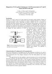
126 8. Model of reactive transport of an oil-soluble chemical in porous mediaexcess of mixture (2 PV) was injected. The average total amount of silicic acid and theaverage fraction of silicic acid in the aqueous phase are given in Figure 8.7 as well. Bothparameters increase with increasing k.0.60.6S wS w0.50.4w w SA x S ww wSA0.50.4w w SA x S ww wSAvalue [-]0.3value [-]0.30.20.20.10.10.00 2 4 6 8PV [-]0.00 2 4 6 8ε 0[kJ mol -1 ]Fig. 8.8: Calculated final values (at t = 20 hours) for the average water saturation S w , amountof silicic acid wwSA × S w and fraction of silicic acid wwSA . In the simulation the batchsize was 2 PV. (left) variation of PV injected. (right) variation of ε 0 .The effect of the injection rate Q on the aforementioned average output parameters isshown in the right-hand graph of Figure 8.7. The rate was varied between 0.02 and 10 mlmin −1 . The final average water saturation decreases with increasing Q. With Q in therange of 0.02 to 0.1 ml min −1 the amount of SA formed is approximately constant. Forvalues of Q greater than 0.1 ml min −1 the amount of SA formed decreases slightly withincreasing Q, given the amount of mixture injected (2 PV).In case of an excess amount of mixture injected the amount of silicic acid formedslightly increases with increasing number of PV injected, the degree of which depends onthe reaction rate k. In this example (k = 0.323×10 −3 s −1 ) the output parameters increasewith an increasing number of PV injected for volumes greater than 1 PV (see Figure 8.8).Obviously, in case less than 1 PV of mixture is injected, not all oil in place is displaced byTMOS/oil so that the amount of silicic acid formed is less than in the previous examples.Similarly, the values for a, ε 0 and D were varied, each within a representative range.The parameters a and D (not shown here) appeared to have a negligible influence on theaverage output parameters. However, the parameter ε 0 has significant influence on themass transfer rate and the average output parameters. It can be observed in Figure 8.8that the final water saturation and the amount of SA formed decrease with increasing ε 0 .8.4.4 Case B. Continuous injection: exampleThe results of one of the simulations for case B are discussed next. The parameters werechosen as follows. The oil/TMOS mixture is injected continuously with a flow rate Q= 0.1 ml min −1 . The diffusion constant D is 10 −10 m 2 s −1 and the reaction constantk is 0.323×10 −3 s −1 . The interaction parameter ε 0 is equal to 2×10 3 J mol −1 K −1 and